This thread has been locked.

If you have a related question, please click the "Ask a related question" button in the top right corner. The newly created question will be automatically linked to this question.

TAS2563YBGEVM-DC: Learning Board not passing audio checks

Part Number: TAS2563YBGEVM-DC
Other Parts Discussed in Thread: TAS2563, TAS2781, PPC3-EVM-MB, TPS61288

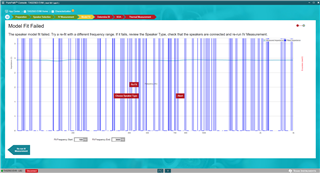
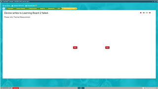
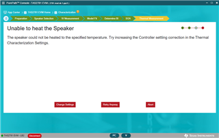
I'm using the TAS2563 EVM and module. It passes audio fine. When I connect the learning board in order to do speaker characterization, the audio checks don't pass, as in this screen:

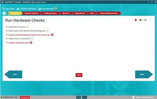
I have verified that the audio settings are indeed 24bit 48KHz. Any suggestions on what to do

  • Hi James,

    this can sometimes happen and usually it will still allow you to complete the characterization process without issue.

    However, Usually unplugging the evm and restarting the machine will allows these checks to pass successfully

    regards,

    arthur

  • Thanks for that, I will try it. In the meantime, I'm struggling with just using TAS2563 EVM and module. It actually doesn't work fine most of time, only some. Most of the time, the audio volume drops considerably, then comes back up, then drops again after 10s of seconds. I've got the limiter, brown out protection, and thermal foldback disabled. It's weird because sometimes it goes for long stretches at the correct volume, but then will drop for no reason. Any thoughts on why?

  • And the problems just keep coming. I am getting "speaker model fit failed" though the sweep can be heard and it looks like it measured impedance, if the graph is to be believed. Any suggestions?

  • Hi James, 

    I am sorry to hear you are having further issues, sometimes ppc3 can fail the checks but still function correctly. in this case it looks like there is some issue in the record path

    the audio could be fluctuation if the speaker Re is not calibrated correctly. the algorithm could be grossly overestimating the speaker temperature. you can check that basic function of the EVM with the device in ROM mode(DSP Bypass). this can be set in the "device control page" if there is no fluctuation when in ROM mode we can assume that issue is related to the incorrect speaker parameters

    The issue with char seems to be in the record path. there are a few things to try

    - make sure the EVM record is not muted in widows sounds settings

    - try a different USB port

    - in device manager disable then enable the TI audio device

    Regards,

    Arthur

  • Arthur, thanks for your replies. I'm making some progress, but still have a few issues.

    1. On first connecting to the TAS2563EVM, I get this screen and wonder if it could account for some of my troubles?

    2. I make it all the way to the last step of characterization, the thermal part, and it fails with this screen. It's not clear what else to try here.

    3. ROM mode. I don't understand what this does. I get this screen and when I click on the ROM Mode box, it says it executes but I'm not sure what is happening or changing. Some clarification here would be greatly appreciated.

  • Hi James, 

    1. On first connecting to the TAS2563EVM, I get this screen and wonder if it could account for some of my troubles?

    this error wont affect the funcitonality of ppc3. the EVM has an eeprom IC on it which stores the boards hardware ID. this ID is only used for the PPC3 homepage to highlight the EVM app for the connected hardware. this error will happen when the EVMs ID is mismatching between the EVM and PPC3. I was under the impression that we had resolved this...

    2. I make it all the way to the last step of characterization, the thermal part, and it fails with this screen. It's not clear what else to try here.

    I do apologize for this inconvenience regarding the advice I can give here. sometimes the record path from the EVM through the USB audio driver and into PPC3 will get messed up in some way, incorrect data, no data etc. typically, the best thing to do here is to unplug the EVM and then replug it and reconnect to ppc3. the characterization wizard will save your progress so there is no need to start from the beginning. 

    3. ROM mode. I don't understand what this does. I get this screen and when I click on the ROM Mode box, it says it executes but I'm not sure what is happening or changing. Some clarification here would be greatly appreciated.

    so, our devices have two operating modes regarding the internal DSP and smart amp functionality.

    ROM mode - this means the devices DSP is completely bypassed. no smart amp protection, EQ, DRC etc. however more basic functions like brownout protection, HPF and limiters will still be enabled. basically any device funciton described in the datasheet will still be available.  we call this "ROM mode" because the default settings burned in the devices ROM have all blocks bypassed.

    Tuning mode (RAM mode) - this is when the DSP blocks have been enabled and the PPC3 GUI has loaded coefficients for the various filters, gain blocks biquads etc into the devices RAM. in the end system the device will be operating in RAM mode 99% of the time

    The reason I asked for you to check in ROM mode is to see if the audio fluctuations you are seeing are due to some incorrect ppc3 default setting which is interacting poorly with your speaker, or if it is some instability issue with the EVM

    Regards,

    Arthur 

  • I am about ready to give up. Here's what I'm observing with just the eval board, no learning board:

    1. If I select test and measurement, I see the ROM mode screen. I assume just selecting this screen puts it into ROM mode. This does get rid of the fluctuations in level. When I go back to Tuning and Audio Processing, the fluctuations start again. I assume from what you said that this puts it back in RAM mode. I've got everything disabled and the fluctuations remain.

    2.If I attach the learning board, then reconnect the software, I can't reliably play audio, even though the sound device is there and my apps think they are playing to it. I can't make it work today at all. When it has, I've been able to get the IV measurement and get past the model fit, but the thermal measurement fails per the last post.

    I've put in a request, last week sometime, for access to the TAS2781 EVM. I've now received that hardware and would like to move on to that one to see if it behaves any better. Can you please approve that request?

  • Hi James, 

    I will escalate this and share it with our software team.  - and yes I will get the marketing team to approve this TAS2781 request ASAP

    Are you willing to ship a few pieces of the speaker to our lab in Dallas and I can perform the characterization for you? If you ship 5pcs I can characterize them and share the parameters with you. from your side it would only require you to measure the speakers resistance and enter it manually in the "Re" speaker parameter.

    Regards,

    Arthur

  • Hi Arthur,

    Thanks for escalating this. My immediate needs are to validate this chip for potential use in a new speaker design, not the one I currently have in front of me, which is a simple 2" driver in a small sealed enclosure. I could send one of these to Dallas if it makes sense, but since my goal is not specifically related to this particular speaker, I'm not sure it makes sense. Please advise on this point.

    A bit more background: the proposed new speaker design would be battery powered with likely two lithium cells, likely in parallel if I can use the TAS2563. This would be used to drive the tweeter. I would then want to use the TAS2781 to driver the woofer in this 2-transducer design.

  • Hi James, 

    thanks for the additional information - 

    One more thing, can you make sure that J15 IOVDD Select on the PPC3-EVM-MB is set to 1.8V? this is required when paired with the LB2.

    Regards,
    Arthur

  • Certainly ppc3 has its quirks, but failing the thermal char consistently is unusual. the Learning Board 2 is only 1.8VIO

  • It was jumpered for 3.3V. I changed it to 1.8V and the same erratic behavior continues. I was able to go farther into the thermal characterization, but the plots weren't changing as my speaker kept getting more and more 16KHz power, so I aborted. It seems it isn't receiving the mic signal reliably.

  • The Thermal characterization is not using the microphone data - it will be recording the estimated temperature via I2S from the device.

    You are seeing that the "input power" plot is climbing but the temperature profile is not? is there no movement as if there is no received data or as if the speaker is only heating very slowly?

  • I see, that makes sense. The power is fixed at 0 and the ambient fixed at 20C. Neither is climbing, yet I can see the VBat power supply current going up slowly as the test progresses. Should I2S and I2C be jumpered to 1.8V as well?

  • No the I2S/I2C jumpers can be 3.3 or 1.8. 

    Could you share a picture of the thermal page when the temperature is fixed at 0?

  • Hi James, 

    I got you approved for the TAS2781 software. you should see it in no more than 30 mins

    Also, I showed this to my colleague and the common 'gotcha' is the IOVDD setting which we have already set to 1.8V. I would ask you to check once more today and see if it can be completed.

    Regards,
    Arthur

  • I verified the IOVDD is set to 1.8V, and ran the thermal test again. Same result. I just received the TAS2781 SW, so I'll switch to that and see how things go.

  • Ok, the TAS2781 set up is work MUCH better. But, I am getting stuck at thermal characterization again, but in a different way. It hangs at finding thermal resistance. If I try to abort, it hangs there saying "aborting". I have to disconnect and reconnect in order keep going. Any thoughts on what to try here? BTW, this setup is playing audio just fine, the EQs seem to be responding, and there is no fluctuations in level as with the TAS2563. Should I start a new thread for this?

    Also, can you clarify what the flex cable Re should be a measure of? I assume the round trip resistance of the speaker feed cable, but should that include the learning board and choke ahead of it, or just from the learning board to the speaker?

  • Actually audio is still fluctuating. I try to go into ROM mode, hit apply, then the app crashes. Any suggestion?

  • Hi James, What OS are you using is it Windows 11? PPC3 is supported up to windows 11, but is it possible for you to try on a different machine?

  • Windows 10 pro. The other computer I have is corporate managed and I can't get PurePath to find available software. It just hangs.

  • One thing I don't understand: do I need to get past characterization steps in order for the amp to behave properly? Is there some way of disabling thermal protection so the amp just runs full tilt?

  • Hi James, 

    I think that the issue we are having here may be caused by the TI USB audio driver, as it seems like the estimated temperature data is being lost. can we try uninstalling the USB driver for the EVM. this can be done when the EVM is plugged in in device manager you can right click -> uninstall. then also uninstall ppc3, then restart the machine and reinstall ppc3. the re-installation of ppc3 will also install the EVM audio driver. 

    With that said...

    the thermal protection cannot be completely bypassed without disabling all DSP features(ROM mode) you do not necessarily need to complete the thermal characterization - with the proper knowledge it can be done manually.

    For TAS2563 the main input to the thermal controller is the Rteq (the speakers equivalent thermal resistance) this value is calculated by ppc3 by using the following equation. the algorithm is only considering Rteq. the ppc3 provides all the other industry standard parameters rtv,rtva,rtm for reference only.

    Rteq = ((rtv + rtm) * rtva)/(rtv + rtm + rtva)

    Rteq is given in kelvin/Watts K/W. a speaker with 100K/W Rteq will heat up by 100kelvin (or 100C) when 1W is played continuously.

    for example if you have a speaker which is 5W rated and its voice coil is rated for 100C. then we can calculate its Rteq as 100K/5W or Rteq = 20

    you can calculate this manually and then arbitrarily select rtv/rtva/rtm until the above equation = 20

    For TAS2781 Rteq is not used. instead you will need to tune the thermal controller manually. the values of interest are PG, IG1, IG2.

    1) set IG1 = IG2 = 0, and make sure speaker Re and TMax(voice coils rated temperature) are entered correctly 

    2) set PG to something low like 0.1

    3) play 0dBFS 4kHz sine tone and record the temperature profile. increase the PG until temperature is rising quickly without any overshoot or pumping/audio fluctuation

    4) repeat steps 3) until the temperature profile of the speaker is reaching within >60% of the speakers TMax. closer to Tmax will be louder, but using a large gain here can cause audio fluctuations and pumping.

    5) make note of the PG value after step 4) we will call this value our "loop gain"

    6)set PG = loopgain * 0.9

    7) set IG1 = loopgain * 0.075

    8) set IG1 = 2*PG

    Regards,
    Arthur

  • I reinstalled as you recommended, and got the thermal characterization to run once. It only got as far as the above. I have not been able to get this to run again, the whole system is far to flaky to use. In case I manage to get it working again, where would I set the PG and IG values?

  • Hi James,

    the "Unable to heat speaker" error can happen if the speaker is larger than a ~1W micro speaker, as PPC3 defaults are intended for smaller speakers.

    You should slightly increase the Controller Gain to something like ~0.03 and also decreasing the "Excitation frequency"  

    the PG and IG gains can be found in "Tuning and Audio Processing" -> "Characterization Data" panel under thermal 

    Regards,
    Arthur

  • I am not able to, most of the time, get audio to play even though Windows thinks it is streaming to the TI audio driver. I did try uninstalling everything and reinstalling. So, I found another Win10 pro machine and set up a new installation. Same issue there, except that I haven't been able to get the audio to work even once. All the comms between PurePath and the board seem to be working, as evidenced by the messaging at the bottom of the frame. Very frustrating. Any suggestions as to what to try next?

  • Hi James,

    I will try sharing with you the newest beta release for ppc3 and see if the behavior is better

    Regards,
    Arthur 

  • Arthur,

    Thanks, I will try it out soon. I made some progress yesterday in that I'm able to reliably connect and operate in ROM mode. Not sure what changed. I haven't tried the characterization again, since that's lower on my priority list. I'm working on configuring the class H parameters. It's kinda working, but  I'm collecting a list of questions which I will post soon.

  • The Class H setup screen is pasted here.

    1. Why are only some of the component values programmable, and not others? The shown schematic values to not match the eval board.

    Below is a screen grab from scope showing a kick drum track, filtered L and R signals are RED and VIO, scaled up by a factor of 2 since the filter has a 6dB loss, in other words the trace represents actual voltage. YEL is the PWMCL feedback pin on the regulator. GRN is the 12V-VBAT rail.

    2. Why is the steady state rail voltage about 11V and not 5V, given the settings in the setup page?

    3. It goes up to about 13V with a bunch of oscillations on top of it. Is this expected?

    I'm planning to use TPS61288 regulator instead of the one on the eval board, so I can get to 18V. But before I patch that in, I'd like to get the existing circuit on the Eval board working as intended.

    Any insights are appreciated.

  • Hi James, 

    The intention here is that the User can enter the R1 resistance and the desired mix max voltages and then the tool will calculate the rest of the RC Values, but this does add a layer of complexity because the tool will recommend values which are not realistic. We will be updating this in future versions.  

    11V nominal doesn't make much sense at all.  Can you reference this thread to see the jumper setting needed to get the class-H working? https://e2e.ti.com/support/audio-group/audio/f/audio-forum/1356483/tas2781evm-standard-config-for-amplifier-evaluation-with-resistive-load-and-apx

    Its beginning to come to my attention that the BOM we selected for this mono EVM is not that great out of the box. I am however building some new hardware for this device which is using the TPS61288 as well (good Choice). If you would like I can share the schematic we intend to use.

    Regards,
    Arthur

  • Thanks, that is helpful. The thread you cite is pretty much the same goal as mine. I am not getting the regulator to work yet. You state there "EVM default voltage will be ~7V. when J14 is inserted the voltage should be ~5V." but in my case PVDDH = 11.5V steady state, and PVDDL = 5V. This doesn't change whether J14 is in or not.

    Here's a big clue: no matter which POW_MODE I select, or whether Class H is ON or OFF, nothing changes. (I am hitting apply afterwards.)

    And perhaps related is I don't understand what some settings are intended to do.

    • Convert VBAT in PVDD in Misc Class D section. Either setting Convert or No Conversion has no effect in this regard.
    • Bypass Enable Method Relative to VBAT 1S or Fixed. Is 1S referring to one Lithium cell?

    How do I load that .cfg file you gave?

  • Hi James, 

    you can run the .cfg file in the I2C monitor. you can find this button on the bottom center of the PPC3 App

    yes, if j14 is removed we expect the boost converter to be outputting 7V default, then the Class-H will modulate it up and down from that point. 

    one question on that point? what is the supply voltage you are giving to the EVM? Im assuming it was 5V?

    the PWR_MODE is choosing which setting for the Class-D Y-Bridge is being used. When PWR_MODE0 is used the class-d will always be switching from  PVDDH. and when PWR_MODE1 is used the device will be switching from PVDDL when the audio is low, and once the expected peak exceeds PVDDL it will start switching to PVDDH. 

    Convert VBAT in PVDD is a setting related to the SAR ADC which can record voltage data from use inside the device and for streaming got the host. you should leave this as its default. 

    the Bypass Enable Method Relative to VBAT 1S or Fixed is setting at what audio level the Class-D will transition from one supply to the other.

    When fixed you can set a digital level at which the supplies switch

    When "Relative to VBAT1s" is selected it will transition based on the audio level of the PVDDL supple as measured by the SAR ADC. it will leave some margin. it will transition when audio will exceed PVDDL*"Class-D Efficiency" - "Relative Threshold Headroom".

    Yes "1s" is referring to a one segment lithium battery, this is a common naming convention because in many systems the lower voltage supply "PVDDL" (or VBAT, VBAT1s) will be connected to single segment lithium batter,

    Regards,

    Arthur

  • Hi Arthur,

    I've made some progress. I was feeding the system with 12V. Once I changed that to 5V the class H is working more like you describe. A couple of things:

    1. I can't get power mode 2 or 3 to work. Once I select them, no audio. I have to go back to power mode 0 to get the audio to come back. Power mode 1 only works if I select it right after power mode 0. Does any of this make any sense?
    2. I don't see a way to import with the I2C monitor window, only export functions. What am I missing?

  • 1. We have one jumper "J9 CAP_GND" which is additional decoupling that is needed when PVDDL is supplied externally to the device. when using PWR_MODE2 this jumper should be removed, otherwise the devices LDO won't come up properly.

    2. at the top of the window" LOG" is selected. you should select "I/O"

    Regards,
    Arthur

  • Arthur, I've hooked up the TPS61288 eval board with modified resistor values per the attached excel spreadsheet. In that, you'll find 2 tabs where the formulas have been solved for the Rfb1 and Rfb2 values as a function of all the other parameters. I used some symbolic algebra to get those, hopefully you'll find them useful (or perhaps you already had them?).

    My setup is now:

    12V supply to Vin on TAS2781

    4V - 5A power supply to VDDL as 1 cell battery substitute, which also feeds the TPS61288 board input, configured to generate 5V-18V per the spreadsheet. It is patched in and is being controlled properly by the TAS2781.

    But, I'm having two issues:

    1. If I use VDDL from the 4V battery supply, I get an over current error as soon as I turn audio up even a little. Not anywhere near maximum.
    2. If I instead use the on board 5V VDDL supply, I can turn the volume up somewhat louder, but then get PVDD UVLO errors.

    I've been experimenting with all permutations of the settings, and can't seem to get past these issues. Would it make sense for you to send me a config file for a 1 cell external PVDDL configuration with the PVDDH coming from the controlled TPS61288 boost?

    Or some clues as to what might be amiss.

    thanks

    TAS2781 class H calcs cleaned.xlsx

  • Hi James, 

    what power mode are you using when these OC and UVLO errors occur? if you use PWR_MODE0 do you still have the same results? 

    PVDDL UVLO threshold is 2V and PVDDH is 2.428V(Programable in page 0 register 0x71) perhaps if it is simple you can check if any transient is causing a dip below this. 

    Regarding the OC. - can you use the 4V battery supply, get the device into the over current state, and then read all page 0 registers and share it with me? there is some hidden bits in here which can give more insight to us. 

    the device can OC for a few reasons, the above test could help us narrow it down

    1)Vdrive/SpeakerR is too large

    2) Speakers backEMF can momentarily be in phase with the Vdrive. this can happen if you push alot of power near the resonance of the speaker

    3) Some parasitics on the power supply can cause ripple and couple into the current comparator circuit and cause an erroneous error

    Can you try with the 4V battery supply and use the shortest and lowest gauge cables you have? it could be that thee cables have too much inductance.

    Regards,
    Arthur

  • Arthur,

    I have tightened up the wiring and seem to be past the last set of issues. Currently running on 7.2V PVDDL and something is shutting down the chip on peaks. None of the flags are going off. I'll send the page 0 info but I can see a way to save or copy it.

  • 7.2V PVDDL? Do you mean PVDDH? we recommend keeping PVDDL at 5V nominal.

    Once you are in the over current state, you can use the I2C monitor "I/O" function and run the below script. then from the I2C monitor copy the output log and share it.

    w 70 00 00 #page 0 on current book

    w 70 7f 00 #book 0

    w 70 00 00 # page 0 book 0

    r 70 00 7f # read 0x7f registers starting at reg0

    Regards,
    Arthur

  • Well, that little fact escaped me and I blew up the chip by applying 7.2V to PVDDL. Oh well, I'll replace it. In the meantime, I think I understadn how the boost control works, with 0% to 100% being open to short circuit (not counting the pullup to IOVDD if present). But is this a closed loop system where the chip monitors PVDDH and uses that to control the duty cycle, or is it instead open loop where the chip assumes 0 to 100% corresponds to the range set in PurePath tool?

  • Hi James, 

    it is an open loop system. there is no feedback from PVDDH which is determining how the device is modulating the external boost voltage. that is all determined by how the class-H function is programmed in PPC3

    Regards,
    Arthur