This thread has been locked.

If you have a related question, please click the "Ask a related question" button in the top right corner. The newly created question will be automatically linked to this question.

TPA3255: Low output power + 50kHz oscillation. (continued)

Part Number: TPA3255

Hi,

with the other thread being locked an missing some replies by me:

We still have the same issue.

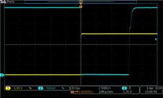
Fault does (Very very briefly) appear on releasing RESET.

Bulk Power decoupling capacitors are Panasonic "VF 470/63 K-J16" - we've tried others

Channel 1: /RESET, Channel 2: /FAULT

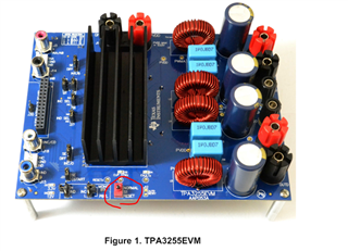
Ref board:
Our Board:
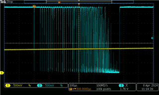
This does not occur again after startup.

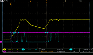
If we run in the faulty state (amp delivering interrupted output)  for a very long time we see extremely brief pulses on Fault:
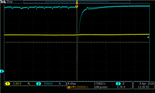
The amplifier never sets OTW, and does not stay in fault under any circumstances.

Greetings, Martin

  • Hello Martin,

    During this startup can you also capture the AVDD voltage. Addtionally do you have a waveform that capture all the voltage rails for the TPA3255?

    best regards,
    Luis

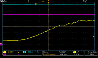
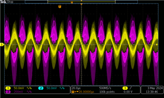
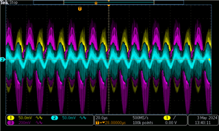
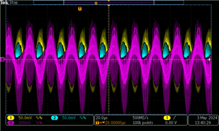
  • Channel 1: AVDD, Channel 2: DVDD, Channel 3: PVDD.
    First screenshot is Startup, the other three are AC-coupled during operation (same data, with the individual channels brought to front)

    Greetings, Martin

  • Hello Martin,

    Was this behavior observed on multiple boards, typically the device startup sequence would have Pin to Pin Short Circuit checks as soon as PVDD VDD/GVDD is provided then that fault would clear, after you clear the reset pin, the Fault pin would be asserted during since it would be UVP in the period AVDD LDO is ramping up then that would clear. 

    I see that in our board but in your board are you changing the reset state at all?, don't see the reset transition in that abnormal fault behavior you are seeing.

    best regards,
    Luis

  • Yes, we see that behaviour on multiple Boards (and with ICs directly received from TI)

    We do drive RESET - as seen in the previous thread (but i'll get some more captures)

    Greetings, Martin

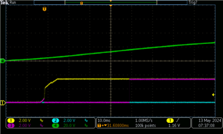
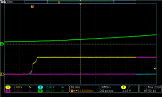
  • We have additionally captured large-scale behaviour on initial PowerUp: (before driving RESET, same power supply between EVM and our board)

    1 = DVDD, 2 = RESET, 3 = FAULT, 4 = PVDD

    Our board:

    TI Board:

    To recreate the "RESET driven by bouncy mechanical switch" situation like it is on the -EVM, see the following:

    (being clear: this is _not_ how we actually use the chip, just to show that behaviour looks like it does on the EVM when we also use a bouncy switch with our board. as you can see,

    outputs closely follow the RESET input even when driven with a very bouncy source)

    1 = AVDD, 2 = RESET and 3 = FAULT

    Greetings, Martin

  • Hello Martin,


    For the last image that was the behavior observed with your system board with the reset switch driven by the EVM? In your actual system is reset being driven by an external IO pin? It's difficult to see in the drawing but what is the PVDD value when the fault is being cleared in the initial powerup behavior?

    best regards,

    Luis

  • The RESET-Pin is held low by a pull-down resistor and driven high by a microcontroller output pin. In the test I used a toggle switch to drive the RESET high to turn the amplifier on without the controller board. Unfortunately the switch is a bit bouncy, but I couldn't notice any differences in the load issue when driving the amplifier with the controller board or with the test-setup. The PVDD voltage is 15.6V when the fault clears on both the EVM and our board.

  • Hello Martin,

    • To confirm, during this abnormal state a significant current draw is seen, based on what was said in the previous thread
    • What is the thermal paste and heatsink used in your system. Is there a picture of how this is mounted in your system
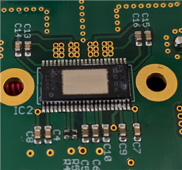
    • Can you provide a physical image of the soldering of this device on the PCB?A possible concern could be regarding the soldering for this system that may manifest in abnormal device behavior. Has there been device swaps on boards that display this issue to see if the same behavior is observed? If you put the IC on these systems where the fault is observed on an EVM would you see the same behavior
    • Could you try a larger C_start capacitor to see if the same behavior is observed
    • For these following startup diagrams you had provided
      This abnormal fault toggling behavior is seen after reset is cleared or before? If you extended the startup sequence would we see the fault toggling seen in the other image?
  • The increased current draw is only observed on the board which oscillates.
    To cool the ICs, they are mounted on the bottom side of the PCB and a copper
    heatspreader is placed between the IC and the chassis. On both sides of the
    heatspreader standard thermal paste is applied.
    All of our boards have the same power-issue. Only the one where I replaced
    the PET-capacitors with PE ones oscillates.
    We used ICs from different lots and all behave the same.
    On the first diagram, this fault toggling behaviour is only seen, when the
    /RESET-voltage ramps up too slowly.

    Picture of board underside with TPA3255 (white residue is non-conductive thermal compound)

  • hi Martin

    about your issue, let me clear some points.

    1. why you avdd has so many sawtooth? the reset pin waveform seems follow the avdd sawtooth movde.

    2.can you describe more detail how you reproduce it on our evm?

    change the reset switch on TI brd to your switcher?

    or having some special power sequence?

  • Hi!

    1) The bouncy RESET waveform is produced by a mechanical switch connected to our board. This is not the normal use (it is usually driven by a microprocessor), we did that to exclude the microprocessor as the fault reason. (this more closely resembles EVM use).

    AVDD follows RESET here.

    2) We cannot reproduce any of our issues on the EVM

  • Hi Martin,

    Could you grab screenshots of your +12V rail used for VDD and your GVDD rails? The GVDD rails power the gate drive and VDD is the supply for the AVDD and DVDD rails. Since the FAULT pin is being tripped and then recovering, this indicates some sort of under voltage detection.

    Regards,

    Ramsey

  • Hi,

    we did three measurements like this:

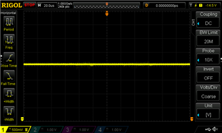
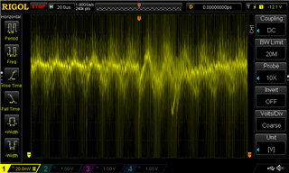
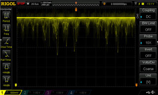
    Before resistor: (500mV/Div and 20mV/Div)

    After Resistor:

    DC Coupled, offset to -13V

    AC coupled, offset by 1500mV

    We see these -2000mV spikes on the GVVD side, even on the non-loaded channel.

  • Hi Martin,

    Please ensure your 12V rail is within spec. Your screenshots show that the 12V rail is over 14V.

    Regards,

    Ramsey

  • It is within spec at 12V exactly , the "-14.2V" is the trigger setpoint (capture was made free-running) (verified with calibrated DMM)

  • Just to confirm, both the 12V rail and GVDD are around 12V? You had mentioned an offset of -13V on the scope and the GVDD was still over a volt above "0".

  • Yes, i'm certain. I re-checked, the "20mV/div" AVDD screenshot is offset by one additional Volt to show the characteristic of the noise better, as you can see on the "500mV/div" screenshot where the offset was -12V we're right on the spec here.

    As GVDD is created from AVDD via the (datasheet-suggested) R (3.3Ω) || C filter it can only be lower.

    Greetings, Martin

  • Understood. Do the dropouts begin immediately as ~100W is played or does it take some time? In addition, do you have screenshots of the output signal, PWM outputs, and the power supplies when the dropouts occur? 

  • Hi,

    the problems begin after a few (single-digit) seconds.

    We're certain that chip temps are not outside limits.

    All screenshots in this (and the previous) thread are under fault conditon, i'll get back to you to get ones that include AVDD/GVDD and PWM and output in the same screenshot.

    Greetings, Martin