This thread has been locked.

If you have a related question, please click the "Ask a related question" button in the top right corner. The newly created question will be automatically linked to this question.

TPA3255: Not zero-crossing square wave in BTL Mode

Part Number: TPA3255

Hello,

I have designed a board that works and performs well, however, it dissipates slightly more than it should on idle (the inductors get warm + the heatsink too).

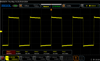
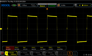
I have noticed by measuring across OutA/OutB and OutC/OutD with differential probe that the square waves are not crossing exactly at zero.
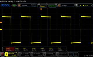
I compared this with a very similar designed board, and in the other one the cross perfectly.

Do you know what components could cause this difference? It appears like the channels have different duty cycle.

It doesn't matter if load is there or not.
Regards,

  • hi,

    can you share me the sch, pvdd voltage, load resistance value?

    usually,

    1.there might be LC difference lead to the 2 channels difference which might lead to large idle current.

    2.pvdd is high and load is small, idle current also might be large naturally.

    tks

    jesse

  • Hi,
    Thanks for getting back to me,


    PVDD is 48V, no input signal (just idle), doesn't matter if the load is connected or not, but generally i use 8R resistive load for testing.

    I understand that the dissipation may be higher at higher PVDD, but when I compare my design to very similar design (same PVDD, same size inductors), in my design inductors reach +50C on idle pretty quick, in the other design they barely heat up.

    PS: By the way, just realized I have 1oz copper, do you think that would matter though for idle operation (the datasheet recommends 2oz).

    Regards,

  • hi SS44

    the copper thickness has highly affect heat dissipation.

    also, let us remove the inductor first to see whether the heat can be soften?

    also, we can use the thermal tester to see which component increase heat fastest on the board.

    tks

    jesse

  • Hi Jesse,
    I got 2oz boards on the way so I will provide feedback if that helps.
    I have removed inductors but the power dissipation went up a bit (from ~5W idle to ~6.7W idle). Bear in mind that I use PFFB, so in this case I broke the loop. Yes, I used thermal camera, the heatsink is warm but not hot (~45C).
    Even without the inductors, I can still see Not zero-crossing in BTL mode at the output of the chip. Is that normal? It's smaller, but present. Is there any way I can adjust it (or do you know what can affect it)?
    Regards,

  • hi SS44

    i am not sure whether this phenomenon can be found on other chip or not?

    we haven't seen this kind of problem before. it seems like comes from high side and low side mosfet unbalance.

    you can check whether bst cap variance affect it or not.

    tks

    jesse

  • Thanks Jesse,

    I have just tested 2oz copper layout - it definitely improves thermal parameters (the inductors are not as hot as before).

    However, the imbalance is still present. I've noticed it changes depending on PVDD (when I change voltage, glitches become bigger/smaller).

    I will try more matched bst caps soon - will provide the results.

  • hi,

    also if you have another chip at hand, you can confirm does this phenomenon follow by chip or follow by board.

    tks

    jess

  • Hi Jesse,

    Yes, I have confirmed that with 3 different chips and the problem persists. 

    I've matched boost caps very close (<1%) and it didn't change the imbalance.

    Worth to mention - the imbalance is pretty small (as per screenshot above), but it grows bigger if I suddenly drop the PVDD on by bench PSU (it dynamically grows bigger and then auto adjusts itself to a certain degree). Could that be related to the capacitance size on PVDD?

    Regards,

  • hi,

    do you have evm at hand, maybe confirm with our evm will help separate this question comes from chip or the board design.

    when pvdd drop down, the voltage drop difference at both half bridge do might lead to different at the output of 2 bridge.

    we still need to distinguish this is caused by external component or the chip.

    tks

    jesse

  • Hi Jesse,

    Unfortunately, I don't have an evm, perhaps someone else would be able to check this.

    Thanks for your help anyway,

    Regards,

  • hi,

    for this is very old evm, i will confirm with our team member whether they have this evm to confirm or not.

    tks

    jesse