This thread has been locked.

If you have a related question, please click the "Ask a related question" button in the top right corner. The newly created question will be automatically linked to this question.

LM51231-Q1: Inquiry Regarding Adjustment of RT Pin Resistance for EMC Improvement.

Part Number: LM51231-Q1
Other Parts Discussed in Thread: TAS5825P

Tool/software:

Hi 

We are using the LM51231Q1 in our audio product for dynamic output voltage management in conjunction with the TAS5825P's Hybrid-mode.

The maximum output power reaches 33W.

The RT pin (switching frequency setting pin) of the LM51231Q1 was originally set with a resistor value of 49.9K ohms.

However, we have observed that this configuration introduces interference that impacts EMC compliance.

By changing the resistor value to 100K ohms, we have effectively mitigated the EMC failure points.

Could you please advise if changing the RT resistor value to 100K ohms necessitates adjustments to other parameters such as inductance selection, loop compensation, and output capacitance?

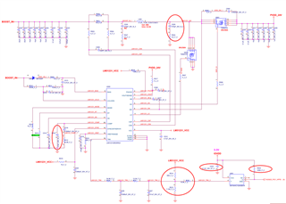
Attached is the schematic of the LM51231Q1 circuit.

Thank you for your assistance.

  • Hello Showfen,

    Thanks for reaching out to us via e2e.

    When you change the RT resistor to 100k, you will reduce the switching frequency from 440kHz down to 220kHz.
    So, the capacitors will need to "bridge" twice the time until they will get re-charged again.
    Also, the inductor will get charged too quickly, to that you may end up with overcurrent and/or DCM mode.
    The current sense resistor and the compensation network will surely need to be adopted as well.

    So, overall it means that you will need an entirely different power stage.

    The QuickStart calculator can help you to calculate all external components.
    You can download it from here: www.ti.com/.../SLVRBJ1

    Best regards
    Harry