This thread has been locked.

If you have a related question, please click the "Ask a related question" button in the top right corner. The newly created question will be automatically linked to this question.

TAS5805MEVM: How to make the continue output power as datasheet?

Part Number: TAS5805MEVM
Other Parts Discussed in Thread: TAS5805M, TAS5805,

Tool/software:

Hi Sir 

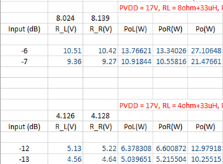
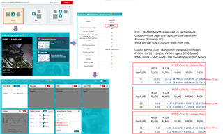
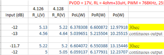
we met some problems on TAS5805M, we would like to measure the efficiency of TAS5805M, but when we gave -15 dB on I2S input. the AMP only operated about 10sec, then it shutdowned.

We saw the error meesage 72h and 73h, it showed OTSD.

But -15dB is about 6W output.

Do we have any method to avoid the OTSD?

Here are our setting as below.

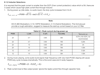
PVDD=20V, 1 TAS5805 stereo for 4 ohm.

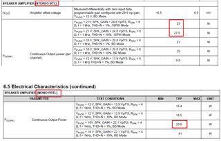
We want to check the value of datasheet as picture below.

Could you please tell me how to config TAS5805 to meet the spec?

and did it add heatsink above of chip? what is the heatsink spec?

  • Hi Simon,

    For the stereo configuration you are using, 8 Ohm loads must be used to hit the boxed values you have shown. With 4 Ohm loads the current through the output FETs is doubled resulting in the device running hotter. The Mono case in the second image uses PBTL so that the increased current is split among two channels.

    Regards,

    Ramsey

  • Hi Ramsey

    Could you provide continuous output power of  4ohm data at THD+N 1% and 10& to us for reference?  BTL mode

    Please use TAS5805MEVM to measure that

  • With a 20V supply and 4 Ohm loads, you will be bound by thermals before you hit 1% or 10% THD continuously. The Max continuous power will depend on your specific configuration, ambient air temperature, and air flow around the device. You can figure out what your specific max output power is slowly stepping up the input level and using a thermal couple on the case of the device to determine when it hits thermal equilibrium.

  • I was able to get 7W/ch for multiple minutes on my setup (default EVM, ferrite bead output filter, stereo 2.0 configuration, 3-band DRC audio mode, 4 Ohm loads, AP used for measurement).

  • Hi Ramsey

    Here is my measurement below.

    The maximum output power in the picture only can work around 30sec.

    My setting is used TAS5805MEVM  (stereo 2.0 configuration, without LC filter, 3-band DRC audio mode, 4 Ohm +33uH loads(or 8ohm +33uH loads), AP used for measurement).

    Ambient temperature is 25C without fans.

    If I used higher voltage (20V), the OTSD trigger point will be faster.

    How could you get 7W/ch output power and keep it for several minutes?


  • Can you send me a picture of your setup and tell me what frequency you are using to test? The results I have gotten are at 1kHz with an un-modified board, resistive loads, and the PPC3 configuration described.

  • Sorry, I will redo experiment (4ohm only) and reply the result afterwards. 

  • Hi Sir

    Here are my test process and test condition as below.

    I had used 4ohm only, but it triggered OTSD faster.

    I had used PVDD=20V, but it triggered OTSD faster.

    I had used BD mode instead of SPW mode, but it trigger OTSD faster.

  • Hi Simon,

    You should not remove the lowpass filter to do these measurements. If the goal is to measure efficiency, you should measure on the device with inductors.

    Regards,

    Ramsey

  • Hi Sir

    I'm confused. For efficiency, wouldn't it be better to remove the low pass filter from the data path?(The low-pass filter still has losses.)

    I measured the voltage and power after the low pass filter but with the load connected directly to the IC output to reduce losses.

  • Hello Simon,

    Use the second(bottom) TAS5805M on the EVM that has the inductors and would be more suited to performance measurements given the voltage level you are using.

    best regards,
    Luis

  • hi Simon

    please change the inductor to 15uH, then that should be able to get your output power. 

    current 4.7uH inductor is not very nice to ripple current which lead to large loss.

    tks

    jesse

  • Hi Sir

    Sorry, I will do this experiment and reply the result afterwards.

  • Hi Sir

    I followed you step, used the second(bottom) TAS5805M and changed the inductor to 15uH, but the result are always the same as the previous data, even the performance was not good as the previous data.

    Here are my measurement below, the first two items are measured through U1 TAS5805 without LC filter

    The last two items are  easured through U2 TAS5805 with L=15uH filter.

    They all operated on SPW mode.

  • 1. please change the fsw to 384k, BW to 80k.

    2. what is the isat of 15uh inductor, please refer the inductor selection section in the datasheet to make sure inductor has enough Isat.

  • Hi Sir

    1. The result was the same as previous.

    2. Isat is 1.05A

  • hi Simon

    - 1.05A is too small.

    when output 6w, 4ohm, the current already be close to 1.22A. 

    please refer inductor selection in the datasheet and chose a inductor which is larger than the maximum current.

    usually, over 3A is very common be used.

    tks

    jesse

  • Hi Sir

    But, even I measured from TAS5805 output directly without filter,just only has AUX-0025 on AP, I'm still not to see the power to 7W.

    And that is I used 17V, experimentation told me that the higher PVDD voltage, the lower the wattage the OTSD would trigger.

    I really doubt that if I change 15uH Isat=2A, the power can run to 7W 20V continuous, could you explain that?

    Because you cane see the picture above, I used 11V for PVDD, the output can do 8.1W although only 30 sec. That is no LC filter.

  • hi, Simon

    remove inductor or using external AUX cannot help this.

    this is because large ripple current still exist and it can go through mosfet that lead to heat.

    using larger inductor can help reducing this. larger isat can also make the inductor value more stable.

    base on our experience, 22uH was used by some of our customer.

    btw, 15uh 2A might not enough. you might need high Isat current inductor.

    tks

    jesse