This thread has been locked.

If you have a related question, please click the "Ask a related question" button in the top right corner. The newly created question will be automatically linked to this question.

TLV320AIC3110: continuous beep on microphone

Part Number: TLV320AIC3110

Tool/software:

Hello everyone,

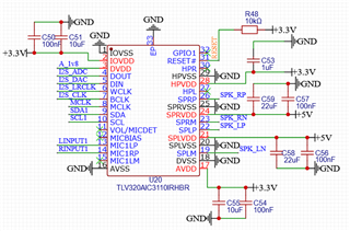
First of all, I want to let you know that I am new to hardware design, so please be gentle. Anyway, I integrated the TLV320AIC3110 into my project, based on the datasheet sample design, and the speaker output works without an issue. However, when I am recording, there is a continuous beep sound. I couldn't follow the suggested layout due to limited space, and I couldn't separate the analog ground and digital ground on my PCB. I placed all the capacitors very close to the codec, but the analog ground and digital ground are mixed.

While debugging, I thought the issue might be related to AVDD power supply noise and separated the AVDD power line from the board, but it didn't work. The system is based on Linux, and I am using kernel driver 6.6.y. I tried many things on the software side, but nothing worked. Could someone help me identify the issue?

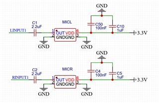
There are two analog MEMS microphones used as capture devices. I tried different mics, but nothing changed. I believe the issue is not related to the microphones.

Thank you!

Sample record in a silence room.

  • Hi,

    Your MIC inputs are going into MIC1LP and MIC1RP, you should AC-Coupled those inputs. 

    Just make sure your audio format is correct along with the clocks etc.

    Regards.

  • Hi, thanks for your help. There are 2.2µF capacitors (as suggested by the microphone manufacturer) on each microphone line, but they are located on another board near the microphones. I checked the PLL clock setting and tried to record at different frequencies, but it didn't help. The recording is working, and I can hear the recorded audio, but there is always a beep sound in the background.

  • Can you send your register configuration (i2c dump) along with the clocks for example mclk, wclk, bclk frequency?

  • The MCLK is 24MHz, and as I mentioned, everything is working, including recording. However, while recording, there is a beep sound in the background. I also checked my capture gain settings via ALSA, but it doesn't affect the beep. The beep volume reduces in parallel with the gain, but this didn't fix the issue. It works like this: low gain equals low beep volume. Thanks for your help.

    This is what I get via I2c dump:

    No size specified (using byte-data access)
    0 1 2 3 4 5 6 7 8 9 a b c d e f 0123456789abcdef
    00: 00 00 01 56 00 11 04 00 00 00 00 01 01 00 80 80 ..?V.??....??.??
    10: 08 00 01 01 80 80 04 00 00 00 01 00 00 00 01 00 ?.?????...?...?.
    20: 00 00 00 00 80 00 00 00 00 00 00 00 00 00 00 00 ....?...........
    30: 00 00 00 02 32 12 03 02 02 11 10 00 01 04 00 14 ...?2??????.??.?
    40: 0c 00 00 00 6f 38 00 00 00 00 00 ee 10 d8 7e e3 ?...o8.....???~?
    50: 00 00 80 00 00 00 00 00 7f 00 00 00 00 00 00 00 ..?.....?.......
    60: 00 00 00 00 00 00 00 00 00 00 00 00 00 00 00 00 ................
    70: 00 00 00 00 00 00 00 00 00 00 00 00 00 00 00 00 ................
    80: 00 00 00 00 00 00 00 00 00 00 00 00 00 00 00 00 ................
    90: 00 00 00 00 00 00 00 00 00 00 00 00 00 00 00 00 ................
    a0: 00 00 00 00 00 00 00 00 00 00 00 00 00 00 00 00 ................
    b0: 00 00 00 00 00 00 00 00 00 00 00 00 00 00 00 00 ................
    c0: 00 00 00 00 00 00 00 00 00 00 00 00 00 00 00 00 ................
    d0: 00 00 00 00 00 00 00 00 00 00 00 00 00 00 00 00 ................
    e0: 00 00 00 00 00 00 00 00 00 00 00 00 00 00 00 00 ................
    f0: 00 00 00 00 00 00 00 00 00 00 00 00 00 00 00 00 ................

    And this is my device tree overlay:

    fragment@1 {
    target-path="/";
    __overlay__ {
    tlv320aic31xx_mclk: tlv320aic31xx_mclk {
    compatible = "fixed-clock";
    #clock-cells = <0>;
    clock-frequency = <24000000>;
    };

    };
    };
    fragment@2 {
    target-path = "/";
    __overlay__ {
    codec_1v8_reg: codec-1v8-reg {
    compatible = "regulator-fixed";
    regulator-name = "tlv320aic31xx_1v8";
    regulator-min-microvolt = <1800000>;
    regulator-max-microvolt = <1800000>;
    regulator-always-on;
    };
    };
    };
    fragment@3 {
    target = <&i2c1>;
    __overlay__ {
    #address-cells = <1>;
    #size-cells = <0>;
    status = "okay";

    tlv320aic31xx: tlv320aic31xx@18{
    compatible = "ti,tlv320aic3110";
    reg = <0x18>;
    #sound-dai-cells = <0>;

    ai31xx-micbias-vg = <0>; // with customized driver

    HPVDD-supply = <&vdd_3v3_reg>;
    SPRVDD-supply = <&vdd_5v0_reg>;
    SPLVDD-supply = <&vdd_5v0_reg>;
    AVDD-supply = <&vdd_3v3_reg>;
    IOVDD-supply = <&vdd_3v3_reg>;
    DVDD-supply = <&codec_1v8_reg>;

    status = "okay";
    };
    };
    };

    fragment@4 {
    target = <&sound>;
    slave_overlay: __overlay__ {
    compatible = "simple-audio-card";
    simple-audio-card,format = "i2s";
    simple-audio-card,name = "tlv320aic31xx-soundcard";
    status = "okay";
    simple-audio-card,widgets =
    "Microphone", "Mic Jack",
    "Speaker", "Speaker",
    "Headphone", "Headphone Jack";
    simple-audio-card,routing =
    "Headphone Jack", "HPL",
    "Headphone Jack", "HPR",
    "Speaker", "SPR",
    "Speaker", "SPL",
    "MIC1LP", "Mic Jack",
    "MIC1RP", "Mic Jack";

    simple-audio-card,cpu {
    sound-dai = <&i2s>;
    status = "okay";
    };
    dailink0_slave: simple-audio-card,codec {
    sound-dai = <&tlv320aic31xx>;
    clocks = <&tlv320aic31xx_mclk>;
    clock-names = "mclk";

    };
    };
    };

  • Your configuration is not correct, the clock settings are mostly powered down.

    0 1 2 3 4 5 6 7 8 9 a b c d e f Comment
    00: 00 00 01 56 00 11 04 00 00 00 00 01 01 00 80 80 4-PLLCLKIN=CODEC_CLKIN=MCLK; 5-PLL down with R=P=1; 6-J=4; 11-NDAC=1 powered down; 12-MDAC=1 powered down; 14-DOSR=128
    10: 08 00 01 01 80 80 04 00 00 00 01 00 00 00 01 00 18-NADC=1 powered down; 19-MADC=11 powered down; 20-AOSR=128; 26-I2S, 16-bits, slave mode.
    20: 00 00 00 00 80 00 00 00 00 00 00 00 00 00 00 00
    30: 00 00 00 02 32 12 03 02 02 11 10 00 01 04 00 14
    40: 0c 00 00 00 6f 38 00 00 00 00 00 ee 10 d8 7e e3
    50: 00 00 80 00 00 00 00 00 7f 00 00 00 00 00 00 00
    60: 00 00 00 00 00 00 00 00 00 00 00 00 00 00 00 00
    70: 00 00 00 00 00 00 00 00 00 00 00 00 00 00 00 00
    80: 00 00 00 00 00 00 00 00 00 00 00 00 00 00 00 00
    90: 00 00 00 00 00 00 00 00 00 00 00 00 00 00 00 00
    a0: 00 00 00 00 00 00 00 00 00 00 00 00 00 00 00 00
    b0: 00 00 00 00 00 00 00 00 00 00 00 00 00 00 00 00
    c0: 00 00 00 00 00 00 00 00 00 00 00 00 00 00 00 00
    d0: 00 00 00 00 00 00 00 00 00 00 00 00 00 00 00 00
    e0: 00 00 00 00 00 00 00 00 00 00 00 00 00 00 00 00
    f0: 00 00 00 00 00 00 00 00 00 00 00 00 00 00 00 00

    You should configure the clock's divider something like this if the sampling is 48KHz as an example.

    Regards.

  • I believe I shared incorrect information regarding the I2C dump. The module was not loaded when I collected that data. If the module is loaded, the I2C dump does not work because it returns the error "Device or resource busy." I have tried to remove the module in various ways, but I haven't been successful because many drivers depend on it, such as snd, snd_pcm, snd_timer, snd_hdmi, and several others.

    I attempted to remove them one by one, but each driver is linked to many more dependencies. As a result, I can't handle obtaining that data after the module is loaded. I am confident that the driver works and sets the registers as expected. My intuition suggests it might be related to the hardware design. I consulted a friend who is using the same codec with the same Linux driver, and they are not experiencing any issues.

    Could you confirm if my schematic design is correct? I am currently redesigning the PCB and trying to separate AGND and GND, as suggested in the datasheet's layout. Do you have any advice? And also if you let me know how to read registers after loading driver, I can share that data as well. Thanks for your support.

  • From the schematic above, I don't see any issue there.

    I'd suggest the following:

    • disable the MIC1LP/RP connection to the ADC through the register, is the tone present?
    • remove the mic connection and provide a tone to the codec mic1LP/RP inputs, is the recording good?

    Regards.