


Other Parts Discussed in Thread: TAS5825M
Tool/software:
Hi Experts,
Good day!
TAS5828M amplifier in hardware mode keeps Fault pin low and produces no sound while I2S signal is present.
I’ve seen similar issues on the e2e forum, but there were no solutions.
I have my own schematic design, but I followed recommended design rules closely.
This issue is somewhat close to mine.
Hardware mode, fault pin low for some reason, no sound.
https://e2e.ti.com/support/audio-group/audio/f/audio-forum/1248421/tas5828m-tas5820m-pbtl-hardware-mode-no-output
Hardware mode, fault pin low for some reason, no sound.
https://e2e.ti.com/support/audio-group/audio/f/audio-forum/1248421/tas5828m-tas5820m-pbtl-hardware-mode-no-output
Here is my partial schematic design.
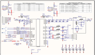
I’m afraid I can’t share the whole sch pdf, as it is a part of a commercial product.
But still I’d like to continue troubleshooting with you.
The faults seem to have been caused by improper startup sequence in Hardware mode.
I have since switched to I2C Software mode. I’m driving both I2C and I2S with a Raspberry Pi as a proof of concept for now. I see all required I2S signals, no fault states but still no sound.
I2C communication seems to work fine both with and without TAS58xx driver.
However, it seems that I need a proper I2C boot sequence for TAS5828M and can’t find it. I have already requested the PPC3 software but I’d really appreciate it if you could provide me with the right way to init the amp.
Attached is the dmesg output concerning the TAS58 amp startup (driver enabled). It seems to boot mostly fine, missing some .bin. Is it critical? Where do I get one? PPC3 maybe? Is the I2C sequence right? If not, I can’t seem to find the place to change it.

Any thoughts and info is greatly appreciated! Thank you so much.
Regards,
Jonathan
