Because of the holidays, TI E2E™ design support forum responses will be delayed from Dec. 25 through Jan. 2. Thank you for your patience.

This thread has been locked.

If you have a related question, please click the "Ask a related question" button in the top right corner. The newly created question will be automatically linked to this question.

TAS2505: Does not work continoulsy

Part Number: TAS2505

Tool/software:

I have a TAS2505 and I am having issues with them. On some units it works perfectly fine but on others it does not. On start-up I play a continuous tone for 10 seconds after initializing the TAS. I have programmed this code on a few devices and have not had any problems thus far. However there are 4 PCBs that only beeps for 1 second then stop. I have checked the clock lines and data lines and compared it to the working boards. Everything is the same. I do not understand why most of my boards but the 4 PCBs just refuse to work as expected. Is there a batch issue I should be aware of?

  • Hi Joash,

    There is no batch issue that we are aware of. The 4 PCBS that are not working, do they have any different features than the working boards? How big was your entire batch? Did you probe the output pins? Thanks.

    Regards,

    Sam

  • Hi Sam,

    All PCBs made are the same. The firmware used is the same across the boards. I have also removed the TAS that is on a working PCB and resoldered it on a non working TSA PCB and the non working PCB now works. So the issue is definitely with the TAS. Your forum did mention having issues with the internal LDO, is this issue resolved? 

    There are no shorts when the IC is soldered. The data is getting to the TAS, I can read back all of the i2c reg, there is no faults as indicated in your ref manual. So the non working TAS is "happy".

    A status flag for OC condition occurrence is provided as a read-only bit on page 1, register 45, bit D1. This reg reads 0x02 when the speaker stops working. In addition there is no over temperature fault condition as well. Like I said this is the same firmware that is loaded on the working PCBs. What else can explain the output from bascially turning "off"?

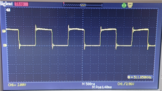
    The normal output of the TAS to the speaker is an approx 240kHz PWM wave. On startup I do see some modulation going on and I do hear the buzzer "beep". However this was suppose to "beep" for 10 seconds, however the modulation only occurs for approx 1 second, then the speaker output reverts to the normal 240kHz PWM non modulated waveform. Hence the "beep" stops.

  • Hi Joash,

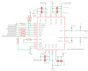
    You may share your schematic so we can take a quick look and check if there's anything that may have been missed.

    LDO fix is not yet implemented on this device (only applied to Q1 version as of now). Our documentation still shows LDO_SEL pin must be pulled to GND.
    However, the LDO issue would show as no audio at all as it is an issue during power on reset; if you have audio for a brief second it would be a different cause.

    If you think it's necessary, you may consider submitting these for failure analysis: Customer returns | Additional information | TI.com

    Best regards,
    -Ivan Salazar
    Applications Engineer

  • Hi Ivan

    Please see below the schematic used. We have the Q1 variant. Can you advise on what I can do to at least narrow down the cause of this? We need a way to test which IC are deemed "faulty".

  • Hi Joash,

    Thanks for the schematic, looks OK.

    I've got a few follow up questions:

    • If you compare the PWM frequency of a "good" vs "bad" unit, is there a difference?
    • What are you writing to the device during initialization?
      • After the problem occurs, if you read the registers do you read the same as you had written initially?
    • Can you inspect the input clocks and data when the problem occurs and compare vs when it doesn't occur?
    • Is the problem always showing on the same device? or is the same device sometimes working and sometimes not?

    Best regards,
    -Ivan Salazar
    Applications Engineer

  • Hi Ivan

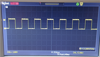
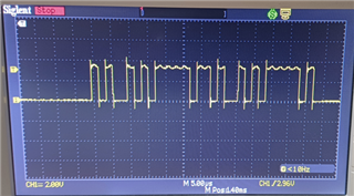
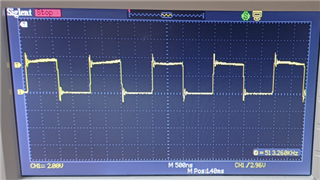
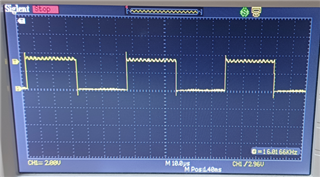
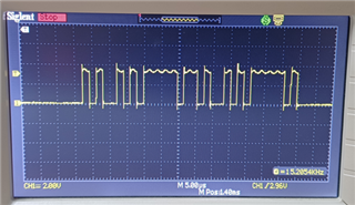
    • If you compare the PWM frequency of a "good" vs "bad" unit, is there a difference? There is no difference noted on the scope.

    Unit that is not working:

    MCLK and BCLK

    WCLK

    DIN

    Working unit:

    MCLK and BCLK

    WCLK

    DIN

    • Is the problem always showing on the same device? or is the same device sometimes working and sometimes not? The issue is always there, even when I reset and reinitialise the device, I hear the 1 second beep (although this was suppose to run for 10 seconds). I say 1 second but its a very short blip. In addition data is still going to the amp. The pics above are taken around 3 seconds after the amp is initialized/ setup.
  • Hi Joash, 

    Thanks for the information, can you please also comment on the register settings?

    What are you writing to the device during initialization?
    • After the problem occurs, if you read the registers do you read the same as you had written initially?

    Best regards,
    -Ivan Salazar
    Applications Engineer

  • Hi Ivan,

    Apologies for that. We have verified that all the registers are identical for each page, with no differences between the instances when it works and when it does not.

  • Hi Joash,

    Understood, thanks for the information.

    I can't think of other things to check, and seems you already did ABA swap test. As mentioned, you can submit these for Failure Analysis if needed.

    Best regards,
    -Ivan Salazar
    Applications Engineer