This thread has been locked.

If you have a related question, please click the "Ask a related question" button in the top right corner. The newly created question will be automatically linked to this question.

TAC5112: DAC 4ch single-ended output setting

Part Number: TAC5112

Tool/software:

Hello, 

I'd like to get 4ch DAC output from TAC5112.

Following is desired signal route:
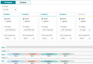
TDM slot 1 -> (DAC1A?) -> OUT1P
TDM slot 2 -> (DAC1B?) -> OUT1M
TDM slot 3 -> (DAC2A?) -> OUT2P
TDM slot 4 -> (DAC2B?) -> OUT2M

I set registers as follows, but OUT1M and OUT2M don't output.
I checked DEV_STS0 value and it was 0xCA, DAC channel 2, 4 were powered down.
Do I need to set any other registers?

Acronym Address Value
PASI_CFG0 0x1A 0x30
PASI_RX_CH1_CFG 0x28 0x20
PASI_RX_CH2_CFG 0x29 0x21
PASI_RX_CH3_CFG 0x2A 0x22
PASI_RX_CH4_CFG 0x2B 0x23
OUT1x_CFG0 0x64 0x24
OUT2x_CFG0 0x6B 0x24
CH_EN 0x76 0xCF

TDM settings:
Frame CLK: 48kHz
Word Width: 32bit
BCLK: 128FS(6.144MHz)

Best regards,

N.SAKAMOTO

  • Hi Sakamoto-san,

    I looked through your registers and it seems that you did not "turn on" your output channels, so maybe the device is only turning on DAC channels 1 and 3. Try to power up all enabled DAC channels after setting CH_EN. To do this, set the PWR_CFG register, address 0x78, set bits 7 and 6 to 1b. Then check DEV_STS0 again and see if that helped.

    You may want to enable dynamic powerup, so channels can be powered up automatically if they are enabled. Check out the DYN_PUPD_CFG register to enable this feature. 

    All the registers you set seem correct for your desired application. Let me know if you need more help with this device. 

    Best,
    Mir Jeffres

  • Thanks for reply!

    I tried turning on DAC channels, but channel 2, 4 don't power up.
    I set registers as follows:
    CH_EN: 0xCF
    PWR_CFG: 0xE0

    And then DEV_STS0 was 0xCA.

    I monitor 4 outputs. OUT1P/2P come out when the device receives FSYNC and BCLK.
    OUT1P/2P are biased around 1.62V. Their DC value seems to be correct but they're very noisy (maybe something is wrong...).
    OUT1M/2M output 0V.

    I also checked diagnostics registers.
    As for outputs, no faults found.
    CHx_LTCH: 0x00
    OUT_CH1_LTCH: 0x00
    OUT_CH2_LTCH: 0x00

    But I found INT_LTCH0 is 0x40, it has an interrupt due to PLL lock.
    Does it cause any output problems?
    How can I fix it?

    Best regards,
    N.SAKAMOTO

  • Hi,

    I think the order in which you set these registers will matter. You want to set CH_EN, then set PWR_CFG, then set OUT1x_CFG and OUT2x_CFG. Then, you can set your PASI registers. Try this and see if it solves your outputs not working.

    I think the PLL lock interrupt is fine, I think it means that the PLL is able to lock with the input clocks (expected behavior for the PLL). 

    Let me know if changing your register setting order does not help your problem.

    Best,
    Mir

  • Hello,

    Thank you for your advice.
    I tried again but the result was the same.
    DEV_STS0 was still 0xCA.
    OUT1M/2M don't output.

    I set registers as follows in this order:
    PAGE_CFG 0x00: 0x00
    SW_RESET 0x01: 0x01
    VREF_CFG 0x02: 0x09
    CH_EN 0x76: 0xcf
    PWR_CFG 0x78: 0xe0
    OUT1x_CFG0 0x64: 0x24
    OUT2x_CFG0 0x6B: 0x24
    PASI_CFG0 0x1A: 0x30
    PASI_RX_CH1_CFG 0x28: 0x20
    PASI_RX_CH2_CFG 0x29: 0x21
    PASI_RX_CH3_CFG 0x2A: 0x22
    PASI_RX_CH4_CFG 0x2B: 0x23

    Other registers are not changed from the reset values.

    When I set output as differential, OUT1M/2M work. OUT1M/2M are alive.
    Stereo single-ended setting doesn't work.
    Are there any specific settings for stereo single-ended?

    Best regards,
    N.SAKAMOTO

  • Hi Sakamoto-san,

    I recorded the steps in PPC3 to turn on all 4 channels and set them to stereo single-ended output. The I2C commands are here:

    w a0 76 ce
    w a0 76 cf
    w a0 78 40
    w a0 78 40
    w a0 78 c0
    w a0 76 ef
    w a0 76 ff
    w a0 78 e0
    w a0 64 24
    w a0 76 ff
    w a0 76 ff
    w a0 76 ff
    w a0 6b 24
    w a0 76 ff
    w a0 76 ff
    w a0 76 ff
    w a0 76 ff

    It looks like I also turned on the 4 input channels, and that is the main difference between our registers. Try turning on all 4 channels, since they are routed to the correct TDM output channels in the PASI_RX_CHx_CFG registers. Maybe the outputs aren't turning on since they do not receive any signal if all 4 ADC channels are not on.

    If this doesn't work, you can try changing the input to be single-ended as well, and see if that helps. Sorry about this difficulty! I hope it works with the simple input channel fix. Let me know if it does not work.

    Best,
    Mir

  • Hello,

    Thank you for your advice.
    I tried turning on the 4 input channels, but OUT1M/2M didn't output.
    I'm sorry for telling you this again.
    DEV_STS0 was 0xFA.

    I also tried TAC5112 EVM and the result was the same.
    Would you check the attached PPC3 settings?

    tac5112_tdm_4ch_single-ended_output.pdf

  • Hi,

    It looks like your output channels 3 and 4 are not getting a TX output - I switched it to "ADC Channel 3" and "ADC Channel 4" and got the last two channels present in the DOUT/TX outputs section of PPC3. 

    The recorded I2C was this:

    w a0 20 22
    w a0 21 23

    It uses the PASI_TX_CH3_CFG register.

    If you run those I2C commands, it may fix your problem. Let me know if it helped or not!

    Best,
    Mir