Tool/software:
Question 1 : Acoustic engineer find sub output have "chichi" noise when play 100Hz signal, ref the following noise wave

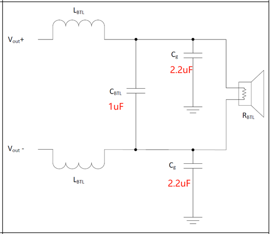
Question 2: TAS5614LA PBTL @BD mode, can you use Cg(1uF) and CBTL (2.2uF) at same time, ref the following setting.

This thread has been locked.
If you have a related question, please click the "Ask a related question" button in the top right corner. The newly created question will be automatically linked to this question.
Tool/software:
Question 1 : Acoustic engineer find sub output have "chichi" noise when play 100Hz signal, ref the following noise wave

Question 2: TAS5614LA PBTL @BD mode, can you use Cg(1uF) and CBTL (2.2uF) at same time, ref the following setting.

Hi Qinghua,
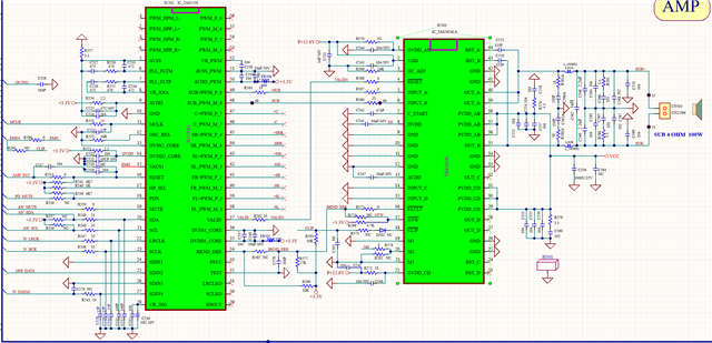
Is the waveform from the EVM or a separate board? I would like to see a schematic of the circuit so I can best help debug. If there is audible noise, it is possible the input has the noise and the amp passes it through, the output filter could be incorrect, or noise is coupled in elsewhere in the design.
The filter you have shown can work in that configuration, but it will depend on the inductor value and output load. Here is a link to a tool to help create an LC filter for your application. https://www.ti.com/tool/LCFILTER-CALC-TOOL
Regards,
Ramsey
Hi Ramsey
Use Eastech new project bord for the test, Pls kindly find attached scematic for you ref.

We have the configuration tool, Can help check the following questions:
Question1: Why Capacitor( CBTL) can't setting?
Question2: If we use Hybrid-AD Mode, how to setting CBTL and Cg?
Question3: If the Quality Factor(Q) high than 0.707, What's the problem will hapen?
Question4: TAS5614LA PBTL @BD mode, can you use Cg(1uF) and CBTL (2.2uF) at same time(ref attached schematic)?
Hi Qinghua,
To use the tool, you need to use the drop down menu at the top to select which filter type. This will allow you to test the necessary values of the capacitors and inductors in section 3 of the tool. You can use section 2 after you configure section 1 to determine what an ideal set of values would be and use that information as a starting point for determining Cbtl and Cg. If the Q is larger than .707, you can start to have an increased gain at high frequencies.
For question 4, the schematic provided is in BTL and not PBTL. For the configuration in the schematic, I would recommend setting Cg to .22uF and Cbtl to 1uF.
I typically see a common mode filter being used with 10uH inductors and 1uF capacitors instead of a hybrid filter for similar applications.
Regards,
Ramsey
Hi Ramsey
Thank you for you feedback.
For BTL @BD output Mode,we adjust Cg to 4.7uF, CBTL to 1uF, Acoustic confirmation of noise level can acceptable.
Is it possible for us to adjust according to such a plan? What might be the problem?
What verification tests do we need to do?
Qinghua
Hi Qinghua,
These capacitor values with the 10uH inductor do introduce a large Q with a 4 ohm speaker, but is probably ok. I would do sweeps of frequency and output power to make sure the performance is as desired.
Regards,
Ramsey