This thread has been locked.

If you have a related question, please click the "Ask a related question" button in the top right corner. The newly created question will be automatically linked to this question.

TLV320AIC3204: Measuring the rms values at the codec output

Part Number: TLV320AIC3204


Tool/software:

Hello Everyone,

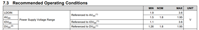
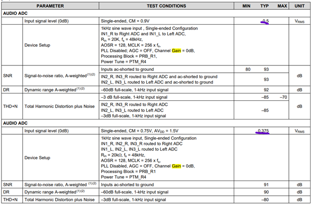
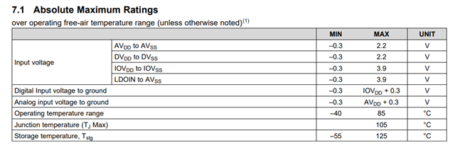
I am working on a project that involves TLV320aic3204 codec. I need to know the maximum and minimum voltage ratings (peak to peak as well as in  rms) to the input IN1L for applying input from the voltage source. I am using codec in mono mode. i need to calculate rms values from minimum to maximum with default conditions.

1. what are the factors included  in this process ?

2. what factors i need to consider ?

3. what are the precaution i need to take ?

4. if Any documents or reference manuals are there. please provide ?

can you tell who has knowledge on this.

Thank you in advance

  • Hi,

    The input rms swing depends on:

    1) AVDD pin voltage: The nominal operating AVDD for the device is 1.8V. For this AVDD voltage, the maximum input signal swing for full-scale ADC output is 0.5Vrms. The minimum operating AVDD voltage is 1.5V, for which the maximum input signal swing is 0.375Vrms.

    2) PGA Gain: The aforementioned values are for a channel gain of 0dB. If channel gain is changed, the maximum input voltage would also change accordingly.

    As precaution, we need to ensure that the device pin voltages do not exceed the Absolute Maximum Ratings.

    We can refer to the device datasheet for more details regarding the same.

    TLV320AIC3204 Ultra Low Power Stereo Audio Codec datasheet (Rev. E) (ti.com)

    Thanks and Regards,

    Lakshmi Narasimhan

  • Thank you Lakshmi Narasimhan,

    1. I need to measure rms value at output side of the codec using software. what registers and values need to configure.

    2. kindly provide if any implementations or calculations on measuring rms with this TLV320AIC3204 or similar codec. 

    3. kindly provide how to configure the registers page 0, page 1 and page 8 using I2C.

  • Hi Eswararo,

    1) You cannot measure rms output value using I2C registers. You must use some kind of external measurement tool.

    2) Is this analog output or digital output? For analog, it's quite straight forward; you could use a scope for this. For digital you will need to use some kind of I2S analyzer tool. Many serial protocol analyzers should support this.

    3) The application reference guide contains a couple of example register set ups. Use these to help determine the register settings needed for your application: https://www.ti.com/lit/ml/slaa557/slaa557.pdf?ts=1724182109287

    Best regards,
    Jeff McPherson

  • Thank you Jeff McPherson,

    1. I am interfacing the TLV320AIC3204 codec to the imx6ull processor. I am giving the signal to the input IN1L from the function generator in milli Vrms and measure the output in milli Vrms using software. The below table-1 are our measuring observations.

    2. My requirement is to measure 0mVrms - 375mVrms codec output for the given input range of        0mVrms - 375mVrms correspondingly whereas the measured output values  as following below table-1.

    FUNCTION GENERATOR RMS(in milli volts) RMS MEASURED Through software ( Normalisation value: 65535) RMS MEASURED Through software ( Normalisation value: 32768) Normalized RMS Peak Value
    100 2 1 -0.7071 -32768
    2 1 -0.7071 -32768
    2 1 -0.7071 -32768
    2 1 -0.7071 -32768
    2 1 -0.7071 -32768
    2 1 -0.7071 -32768
    200 2.044738 1.022369 -0.7071 -32768
    2.044735 1.022367 -0.7071 -32768
    2.044732 1.022366 -0.7071 -32768
    2.044729 1.022365 -0.7071 -32291
    2.044718 1.022359 -0.7071 -29100
    2.044741 1.022371 -0.7071 -32291
    300 2.164587 1.082294 -0.7071 -32768
    2.164577 1.082289 -0.7071 -32768
    2.164617 1.082309 -0.7071 -31807
    2.164615 1.082308 -0.7071 -25888
    2.164537 1.082269 -0.7071 -22074
    2.164628 1.082314 -0.7071 -22074
    330 2.205194 1.102597 -0.7071 -32768
    2.205173 1.102586 -0.7071 -32768
    2.205221 1.10261 -0.7071 -32768
    2.205226 1.102613 -0.7071 -32768
    2.205171 1.102585 -0.629545 -29174
    2.205085 1.102542 -0.4786 -22179
    340 2.139554 1.069777 -0.432507 -20043
    2.141063 1.070532 -0.423617 -19631
    2.143607 1.071803 -0.499683 -23156
    2.141215 1.070608 -0.678076 -31423
    2.139747 1.069874 -0.7071 -32768
    2.138833 1.069416 -0.7071 -32768
    400 1.571934 0.785967 -0.331496 -15362
    1.5742 0.7871 -0.436715 -20238
    1.573271 0.786636 -0.602852 -27937
    1.573556 0.786778 -0.7071 -32768
    1.574781 0.787391 -0.7071 -32768
    1.574755 0.787378 -0.7071 -32768
    1.574915 0.787458 -0.7071 -32768
    500 1.361765 0.680882 -0.592084 -27438
    1.357443 0.678722 -0.321117 -14881
    1.359474 0.679737 -0.199347 -9238
    1.358088 0.679044 -0.198289 -9189
    1.35961 0.679805 -0.31734 -14706
    1.355823 0.677912 -0.587142 -27209

                                                                                         Table-1

    3. The codec data is interfaced through the I2S lines from codec to imx6ull processor.

    4. In the above configuration, for Device setup. All configurations are set as per above Device setup in single-ended, CM=0.75 AUDIO ADC configuration, except MCLK and PLL Disabled.

                         In Our configuration MCLK is 36.86MHz which is approx 3 times of 12.88MHz and PLL is in enable. 

    5. Kindly provide any implementations to get as per our requirement.

    6. kindly share if there are any possible examples or references.

    7. Kindly share if any measurements are done on this using some other techniques like you said above I2S analyzer. if possible share the measuring values.

  • Hi Eswararo,

    I will provide an update on this thread by tomorrow.

    Thanks and Regards,

    Lakshmi Narasimhan

  • Thank you Lakshmi Narasimhan,

    kindly provide if any other possible ways to calculate rms along with above discussions.

  • Hi Eswararao,

    I am unable to completely understand the table shared above. can you help clarify on:

    1) What is referred to as "RMS measured through software (Normalization value = 65536/32768)" and "Normalized RMS"?

    2) Can you share the configuration script that has been used during this testing?

    Thanks and Regards,

    Lakshmi Narasimhan

  • sure Lakshmi Narasimhan,

    1. Actually i am calculating RMS value of applied input at codec input IN1L using ALSA API's which collects raw data from mic and store it in buffers in software. from that buffers we calculate the RMS by squaring and averaging the raw data.

               After squaring and averaging, The value is normalized to [0-1v] with a value of 32768 since it is a 16bit. for [-1 to 1v] the normalized value is 65535. I don't know whether it is correct or not if you have any idea on this kindly clarify.

               I interfaced the codec to imx6ull processor. Using software I am doing above project.

    2. I didn't have any configuration. I simply connect the codec to processor and doing the calculations as mentioned above. I don't have much knowledge on how to configure the codec. my requirement is to calculate the rms value of applied input using software. for that purpose what factors and what gains i need to consider and how to access and modify it. kindly share how to do this.

    3.if possible, kindly share the linux tools to access all page registers through command line for modifications.

  • Hi Eswararao,

    When we are doing 16-bit capture of a sine signal, the peak code can change from -32768 to 32767. For a full-scale sine wave (1 in 0-1), the rms of the captured data should be roughly (32768/sqrt(2)). So, when we take the sine data which is squared and averaged, to normalize it to (0-1) in terms of rms, we need to divide w.r.t (32768/sqrt(2)).

    As per datasheet, the full-scale input can be 375mVrms, so a normalized 1 using above method should correspond to a 375mV rms measurement.

    Also, based on the explanation above, the table is indicating that the measured rms is lower when the signal generator amplitude is increased, which seems counter-intuitive. Is it possible to maybe share raw captured data from the device for the same?

    Thanks and Regards,

    Lakshmi Narasimhan

  • Thank you Lakshmi Narasimhan,

    Actually I didn't capture any raw data. I got the values by running the code and paste it in excel, that values above are shared to you. if possible did you have any mathematical calculations on rms measuring using this TLV320AIC3204 codec to processor. kindly share.

    The RMS are calculated by squaring , averaging and applied square root to the  buffered data from PCM ALSA API's. Is there any approach to calculate rms instead of above. if possible kindly share.

  • Hi Eswararao,

    I will share an update on this thread by early next week.

    Thanks and Regards,

    Lakshmi Narasimhan

  • Thank you Lakshmi Narasimhan,

    If possible any implementations are done on this kindly share.

  • Hi Eswararao,

    The method you have mentioned to calculate RMS:

    The RMS are calculated by squaring , averaging and applied square root to the  buffered data from PCM ALSA API's.

    Is it possible to share the buffered data which is given to the ALSA APIs for calculation?

    Also, is it possible to share a i2c register read dump of the AIC3204 device?

    Thanks and Regards,

    Lakshmi Narasimhan

  • Thank you Lakshmi Narasimhan,

    I configured as per above configuration of codec for 375mVrms full scale 0dB.

    I don't know how to configure page -1 registers of the codec using I2C. May I Know how to configure  registers using I2C. if possible kindly provide commands to configure the codec registers using command line.

    Using alsamixer, I set the ADC level dB gain to 0dB, PCM Level dB gain to  -17dB, Mic PGA is in off, AGC is in off, PGA Level dB gain to 0dB. These configurations are done.

    The codec is configured in mono mode, AOSR is 128, The data from codec input is configured to imx6ull processor through I2S lines.

    1. I need to know the linearity of input applied signal to output measured signal in rms. For this, any configurations shall i need to be configured.

    2. Can you give if you have any configurations for Mono mode configurations of codec.

    3. For this what registers I need to configure. Already I saw application reference manual but I need to know any example configurations as references for my requirement.

    Thanks in advance.

  • Hi Eswararao,

    Apologies for the delay in responding.

    The Register 0x00 corresponds to page selection.

    By writing this register to 0x01, we can then access the registers that are present on page1 of the device register map. This applies to other pages as well.

    You have mentioned the alsa mixer settings in the above post. Can you share the I2C dump of the register values of the programmed page 0 registers during this testing?

    Also, as mentioned in previous post, it would also help if we can access the buffered ADC data (i.e the data which is fed to the API that gives out rms value) for some of the readings mentioned in the table.

    Thanks and Regards,

    Lakshmi Narasimhan 

  • Thank you Lakshmi Narasimhan,

    here the register configuration,

    Register configuration of codec TLV320AIC3204

    page 0:

       0  1  2  3  4  5  6  7  8  9  a  b  c  d  e  f    0123456789abcdef
    00: 00 00 60 00 03 91 07 14 90 00 00 82 88 00 80 02    ..`.?????..??.??
    10: 00 08 82 88 80 01 00 04 00 00 01 00 00 01 84 00    .?????.?..?..??.
    20: 00 00 00 00 c4 00 11 00 00 00 00 00 00 00 00 00    ....?.?.........
    30: 00 00 00 00 00 12 03 02 02 00 00 00 01 01 00 18    .....????...??.?
    40: 0c de de 00 6f 38 00 00 00 00 00 ee 10 d8 7e e3    ???.o8.....???~?
    50: 00 c0 00 00 00 00 00 00 7f 00 00 00 00 00 00 00    .?......?.......
    60: 7f 00 00 00 00 00 00 00 00 00 00 00 00 00 00 00    ?...............
    70: 00 00 00 00 00 00 00 00 00 00 00 00 00 00 00 00    ................
    80: 00 00 00 00 00 00 00 00 00 00 00 00 00 00 00 00    ................
    90: 00 00 00 00 00 00 00 00 00 00 00 00 00 00 00 00    ................
    a0: 00 00 00 00 00 00 00 00 00 00 00 00 00 00 00 00    ................
    b0: 00 00 00 00 00 00 00 00 00 00 00 00 00 00 00 00    ................
    c0: 00 00 00 00 00 00 00 00 00 00 00 00 00 00 00 00    ................
    d0: 00 00 00 00 00 00 00 00 00 00 00 00 00 00 00 00    ................
    e0: 00 00 00 00 00 00 00 00 00 00 00 00 00 00 00 00    ................
    f0: 00 00 00 00 00 00 00 00 00 00 00 00 00 00 00 00    ................


    page 1:

     0  1  2  3  4  5  6  7  8  9  a  b  c  d  e  f    0123456789abcdef
    00: 01 00 01 00 00 00 00 00 00 00 00 10 08 00 00 00    ?.?........??...
    10: 14 14 40 40 00 00 00 00 00 00 00 00 00 00 00 00    ??@@............
    20: 00 00 00 00 00 00 00 00 00 00 00 00 00 00 00 00    ................
    30: 00 00 00 00 40 00 40 00 00 40 00 80 80 00 03 00    ....@.@..@.??.?.
    40: 00 00 00 00 00 00 00 00 00 00 00 00 00 00 00 00    ................
    50: 00 00 00 00 00 00 00 00 00 00 00 00 00 00 00 00    ................
    60: 00 00 00 00 00 00 00 00 00 00 00 00 00 00 00 00    ................
    70: 00 00 00 00 00 00 00 00 00 00 00 00 00 00 00 00    ................
    80: 00 00 00 00 00 00 00 00 00 00 00 00 00 00 00 00    ................
    90: 00 00 00 00 00 00 00 00 00 00 00 00 00 00 00 00    ................
    a0: 00 00 00 00 00 00 00 00 00 00 00 00 00 00 00 00    ................
    b0: 00 00 00 00 00 00 00 00 00 00 00 00 00 00 00 00    ................
    c0: 00 00 00 00 00 00 00 00 00 00 00 00 00 00 00 00    ................
    d0: 00 00 00 00 00 00 00 00 00 00 00 00 00 00 00 00    ................
    e0: 00 00 00 00 00 00 00 00 00 00 00 00 00 00 00 00    ................
    f0: 00 00 00 00 00 00 00 00 00 00 00 00 00 00 00 00    ................

    I reviewed with the datasheet but i didn't get clarity about how to get exact applied rms at output side. if any register values need to change kindly clarify.

    If any points need to be consider for my requirement kindly inform.

    Thanks in advance.

  • Hi Eswararao,

    For setting up the ADC for rms measurement, you can try the attached configuration script for reference. It would configured for the 0.375Vrms condition mentioned in datasheet.

    This configuration is derived from section 4.0.4 of the TLV320AIC3204 Application Reference Guide application note, with below changes:

    1) The MCLK is taken to be 36.86MHz (as mentioned in a previous note in the thread, 3x of 12.288MHz), so NADC is set to 3.

    2) For 0.375Vrms swing, input common mode is set to 0.75V

    As per the referred configuration, the PLL is disabled.

    Assumption AVdd = 1.8V, DVdd = 1.8V MCLK = 36.864MHz Default settings used. PLL Disabled I2S
    Interface with 16bit Word Length. AOSR 128 PRB_R1 PTM_R4
    # Initialize to Page 0
    w 30 00 00
    # S/W Reset to initialize all registers
    w 30 01 01
    # Power up NADC divider with value 3
    w 30 12 83
    # Power up MADC divider with value 2
    w 30 13 82
    # Program OSR for ADC to 128
    w 30 14 80
    # Select ADC PRB_R1
    w 30 3d 01
    # Select Page 1
    w 30 00 01
    # Disable Internal Crude AVdd in presence of external AVdd supply or before
    # powering up internal AVdd LDO
    w 30 01 08
    # Enable Master Analog Power Control
    w 30 02 00
    # Set the input common mode to 0.75V
    w 30 0a 40
    # Select ADC PTM_R4
    w 30 3d 00
    # Set MicPGA startup delay to 3.1ms
    w 30 47 32
    # Set the REF charging time to 40ms
    w 30 7b 01
    # Route IN1L to LEFT_P with 20K input impedance
    w 30 34 80
    # Route Common Mode to LEFT_M with impedance of 20K
    w 30 36 80
    # Route IN1R to RIGHT_P with input impedance of 20K
    w 30 37 80
    # Route Common Mode to RIGHT_M with impedance of 20K
    w 30 39 80
    # Unmute Left MICPGA, Gain selection of 6dB to make channel gain 0dB
    # Register of 6dB with input impedance of 20K => Channel Gain of 0dB
    w 30 3b 0c
    # Unmute Right MICPGA, Gain selection of 6dB to make channel gain 0dB
    # Register of 6dB with input impedance of 20K => Channel Gain of 0dB
    w 30 3c 0c
    # Select Page 0
    w 30 00 00
    # Power up Left and Right ADC Channels
    w 30 51 c0
    # Unmute Left and Right ADC Digital Volume Control.
    w 30 52 00

    I have also attached a sample raw data obtained from an I2S analyzer.

    TLV320AIC3204_Sample_I2S_Capture.csv

    In the data, -1 to 1 corresponds to signed 16-bit ADC data.

    You can try the I2C writes as per the attached script and check the rms measurement.

    It would also help if you can share a raw data sample like the one in the attachment (If not a -1 to 1 scaled data, even direct 16-bit ADC code should be okay).

    Thanks and Regards,

    Lakshmi Narasimhan

  • Thank you Lakshmi Narasimhan,

    I understood the above script I have to know one more doubt. Can I calculate DB using above data if possible can you share how to calculate the dB. My further requirement is measure a Noise levels in dB. Kindly provide how to implement.

    Regards,

    N Eswara rao.

  • Hi Eswararo,

    For a sine input, when giving full-scale signal (0.375Vrms), the peak of the sine wave will be +/-1 (normalized peak). Since the peak code is +/-1, the rms for a full-scale sine input will be 0.707 (peak/sqrt(2)).

    Basically, for the previous attached sine wave capture, we can use 20*log(rms code/0.707) to get the rms of the sine signal in dB

    Thanks and Regards,

    Lakshmi Narasimhan

  • Thank you Lakshmi Narasimhan,

    When I am seeing in some blogs they given 0.00002 as a reference value. Here you said 0.707, will I get exact dB as like measuring dB meter or nearly +-3db with dB. I configured Mems mic to this TLV320AIC3204 Codec and I do the dB calculations. If possible can you give one more data, I need equivalent ADC values for input of 10mv-375mv.

    Regards,

    N Eswara rao.

  • Hi Eswarao,

    Based on my understanding, the 0.00002 is 0.00002 Pa used for reference value to convert sound pressure level to dB. What I have mentioned is the reference level for a sinusoidal signal of peak amplitude equal to 1.

    The above computation that I have given can be used to derive the rms input voltage given to the ADC. eg. If the above computation gives 0dB that would mean that the input rms voltage to the ADC is 0.375V. Similarly, if the above computation resulted in ~-31.5dB, the input rms voltage to the ADC would be 10mV.

    Thanks and Regards,

    Lakshmi Narasimhan

  • Thank you Lakshmi Narasimhan,

    Actually i didn't have I2S analyzer for taking the ADC data directly from the codec. If Possible can i get the ADC values which is equivalent of  10mv,20mv,30mv,40mv,50mv,60mv,70mv,80mv.........375mv values at applied input side. Actually I need to compare the my output code ADC values with the output of I2S analyzer.

    If possible kindly share the ADC Equivalent value of applied above analog voltage values in an excel sheet using I2S analyzer.

    After this I convert this ADC values in rms then calculate the dB with formula 20*log(rms code/0.00002) or 20*log(rms code/0.707).

    My doubt is, can we map exactly or approximately with the dB meter values whether it is dBA or dBC or dBZ.

    Do you have any implementations like this for dB measurement from the mic signals. kindly provide.

    I really appreciate your support.

    Regards,

    N Eswara rao.

  • Hi Eswararao,

    When you refer to dB meter, is it for direct sound measurement?

    Basically, we can map the ADC's rms code to an rms input voltage, for which we can do 20*log(normalized rms code/0.707).

    If the idea to map this rms voltage back to sound level?

    Thanks and Regards,

    Lakshmi Narasimhan

  • Thank you Lakshmi Narasimhan,

    I done with the above equation  "20*log(normalized rms code/0.707)". I didn't get the values of dB measurement as dB meter. The values from 75-80dB above values are nearly mapped as same as dB meter with +- 3dB but below 75 dB levels are not getting exactly. What was the possible reasons?

    My requirement is to design the dB meter that measures the values as like dB meter. If do you have any implementations kindly share.

    Regards,

    N Eswara rao.

  • Hi Eswararao,

    I done with the above equation  "20*log(normalized rms code/0.707)". I didn't get the values of dB measurement as dB meter

    Was this done on the captured ADC data? Is it possible to share a table of measurements (basically if we are giving rms signal input, rms voltage input, ADC rms code and dB converted value, kind of similar to the table you had shared earlier)?

    Just to add some more detail, basically, when the ADC sees an input signal of 0.375Vrms, the ADC output corresponds to a normalized RMS code of 0.707 full-scale.

    If the normalized RMS code from ADC is, say 0.1 RMS full-scale, that would correspond to an input rms voltage of (0.1/0.707) * 0.375 Vrms ~ 53mV rms input to the ADC.

    The above dB computation is relative to the full-scale rms code of the ADC itself.

    If we are looking to get readings like a dB meter, the rms voltage given to the ADC also may need to be translated to loudness (i believe this is the end use case, please correct me if i am wrong).

    Thanks and Regards,

    Lakshmi Narasimhan

  • Thank You Lakshmi Narasimhan,

    I Understood your explanation, upto my understanding I done these calculations

    DB Value Rms Value
    75.5565 0.11991
    76.768948 0.137872
    77.488919 0.149788
    77.027526 0.142039
    80.040449 0.200934
    81.757388 0.24485
    82.108481 0.254949
    82.023268 0.25246
    81.616618 0.240913
    83.545016 0.300802
    84.363985 0.330544
    85.198813 0.36389
    84.878828 0.350729
    84.698415 0.343519
    86.417057 0.418681
    86.065649 0.40208
    86.759719 0.435528
    87.010978 0.448311
    86.613609 0.428263
    89.109428 0.570823
    89.197699 0.576654
    89.079038 0.568829
    88.976128 0.56213
    88.959759 0.561071
    89.543358 0.600064
    89.559879 0.601207
    89.612035 0.604828
    89.623403 0.60562
    89.625738 0.605783
    91.016974 0.711015
    91.171651 0.72379
    91.618722 0.76202
    91.872656 0.784626
    91.739251 0.772667

    Here I am taking the reference value is 0.00002. The mic (Mems Mic is used) output is directly connected to the codec input IN1L in single ended configuration.

    Sorry for a small misunderstanding Actually I configured single-Ended, CM=0.9,

    The above table shown DB values and rms value what I got can you check whether it is correct or not if possible. I gave 1KHz test tone near the mic and captured the above shown table data.

    while Testing I didn't give any gains. Under normal conditions I done this.

    In the calculations I normalized the ADC value with 32768. after that I converted into rms and then calculated the dB values.

    Kindly share, is any mistakes are there?

    if you have any implementations like this share it.

    I need to Measure the Noise levels in dB.

    Regards,

    N Eswara Rao.

  • Hi Eswararao,

    From the rms code obtained from the ADC (I believe that is the values on the second column), we can obtain the rms input voltage (let's call this rms voltage as "X" Vrms) to the ADC using 0.375Vrms as reference full-scale input (or 0.5Vrms, depending on whether we are using 0.9V CM or 0.75V CM).

    This rms can be converted to microphone loudness (dBSPL) based on sensitivity spec of the MEMS microphone being used.

    Eg. Below is a snapshot showing typical sensitivity for one type of MEMs microphone:

    The sensitivity specified is -38dBV per Pascal. This translates to ~12.6mVrms/Pascal.

    So, the sound pressure level in Pascal, can be calculated as ("X" Vrms/0.0126 Vrms) for the specific microphone.

    This can then be converted to dBSPL using 0.00002Pa as reference.

    This sensitivity spec will be mentioned in the datasheet of the microphone being used.

    Thanks and Regards,

    Lakshmi Narasimhan

  • Thank you Lakshmi Narasimhan,

    I understood your above explanation. if possible, Can you give some example dB calculation values in a table from 0.1Vrms to 0.5Vrms applied input to the codec.

    I got complete clarity from your above explanation how the calculations to be done. Once again thank you for your Support.

    Regards,

    N Eswara rao. 

  • Hi Eswararao,

    Do we have specifications for the microphone being used in the end application (like the sensitivity example I have mentioned in the above post?

    Thanks and Regards,

    Lakshmi Narasimhan

  • Thank you Lakshmi Narasimhan,

    below the link provides the specifications of Mems MIC.

    https://invensense.tdk.com/wp-content/uploads/2016/02/ICS-40619-Datasheet.pdf

    if possible kindly give some dB values of applying from 10mv to 100mv.

    Regards,

    N Eswara rao.

  • Hi Eswararao,

    Based on the shared microphone datasheet, here are a few example calculations for estimating dBSPL levels from mic voltage:

    Mic Output voltage (mV) Mic Sensitivity (dBV/Pa) Mic Sensitivity (mV/Pa) Calculated SPL (Pa) Calculated dSPL
    10 -38 12.59 0.794281176 91.97888548
    20 -38 12.59 1.588562351 97.9994854
    30 -38 12.59 2.382843527 101.5213106
    40 -38 12.59 3.177124702 104.0200853
    50 -38 12.59 3.971405878 105.9582856
    60 -38 12.59 4.765687053 107.5419105
    70 -38 12.59 5.559968229 108.8808463
    80 -38 12.59 6.354249404 110.0406852
    90 -38 12.59 7.14853058 111.0637357
    100 -38 12.59 7.942811755 111.9788855

    This is for the condition mentioned in the datasheet (1kHz).

    Thanks and Regards,

    Lakshmi Narasimhan

  • Thank you Lakshmi Narasimhan,

    I Understood above explanations and I cross checked my values. I got same values as like mentioned above but These values are not equal to the readings in the dB meter. In dB meter under normal conversation shows a values in 60dB but our values shows 78-79 dB.  if Possible can you clear this point and I need to Measure a values like dB meter.

    Regards,

    N Eswara rao.

  • Hi Eswararao,

    Can you confirm the unit measurement of the decibel meter you are using? Is it dB or dBA (sound pressure level)?

    If possible can you also compare with 1kHz tone?

    Thanks and Regards,

    Lakshmi Narasimhan

  • Thank you Lakshmi Narasimhan,

    we are using dBA / dBC meter. we are measuring the values by playing 1KHz tone using mobile at the mic

    Regards,

    N Eswara rao

  • Hi Eswararao,

    Based on my understanding of dBA/dBC meters, the measured values are for A-weighted/C-weighted audio signals. So, before doing rms measurement, we may need to apply the weighting filters on the recorded data and then measure the rms.

    Thaks and Regards,

    Lakshmi Narasimhan

  • Thank you Lakshmi Narasimhan,

    if possible can you give any sample software for implementation.

    Regards,

    N Eswara rao.

  • Hi Eswararao,

    Today is a holiday in India, so Lakshmi will be able to get back to you tomorrow.

    Thanks for your patience,
    Jeff McPherson

  • Hi Eswarao,

    We don't have a software sample for this. The weighting filters themselves are described in this wiki:

    https://en.wikipedia.org/wiki/Weighting_filter

    Thanks and Regards,

    Lakshmi Narasimhan

  • Thank you Lakshmi Narasimhan,

    Really I appreciate your support. your support helped me a lot. Thank you.

    Regards,

    N Eswara rao.