This thread has been locked.

If you have a related question, please click the "Ask a related question" button in the top right corner. The newly created question will be automatically linked to this question.

TAC5212: Incremental mode

Part Number: TAC5212

Tool/software:

I'm interested in obtaining high-resolution DC measurements with the TAC5212, and the datasheet briefly mentions an "incremental mode" for this purpose.  Can you please provide some more detail on this mode, and how to best use the TAC5xxx parts for DC measurements in general?

  • Hi Timothy,

    Further documentation on this feature is still in progress, please wait as I contact our validation and design team on more information to assist you. I will update this thread next week.

  • Hi Timothy,

    IADC has multiple modes and configurations, ADC_CH_CFG (page 0 register 81) has the details here. This feature can be used with single-ended inputs.

    In One shot mode it takes one measurement on trigger and holds that value, we also have sequential mode where it samples continuously and you have to do reg write to hold the data (P1_R85) for a manual read back

    The script below is for single-ended, DC coupled configuration. Default NSKIP,NRESET, & OST. One shot single channel mode.

    w a0 00 00
    w a0 01 01 
    w a0 02 09
    w a0 50 48 # Single Ended DC Coupled 
    w a0 55 48 # Single Ended DC Coupled
    w a0 51 80 #Enable IADC in single channel one shot mode 
    w a0 4C 26 # Config for IADC parameters can try different values 
    w a0 76 80 # enabling first channel of ADC 
    w a0 1F 01 # Disabling DOUT for channel 2
    w a0 00 01 # page change 
    w a0 55 08 # Enable IADC diag reg 
    w a0 00 00 #Page Change 
    w a0 78 80 # ADC power up 
    
    w a0 51 90 # Start IADC one shot Conversion
    r a0 51 01 # Reg read to get conversion status
    w a0 00 01 
    r a0 62 03 # Read IADC 24 bit output 

    After you get the 24 bit output from the register read back take a 2’s compliment of that number convert that to decimal and plug that in the equation below in place of vin1p this should give you the measured dc voltage.

    ((vin1p-vin1m)/vfs)*0.925*2^22, where vfs=2.828, vin1m=0 since single-ended and 5k impedance mode

  • Thanks!  If one-shot mode is not needed, and instead a DC-coupled input is to be converted continuously at the rate set by BCLK, etc., is incremental mode needed at all, or is setting DC coupling and disabling low-pass filtering all that is required?

  • Hi,

    I'm not following. You don't want to use IADC to measure DC voltage of INx?

    You just want to send a AC signal, in dc coupled configuration, and don't want to lose the input values at low frequencies? If so, yes that shouldn't be a problem. Just ensure that if negative voltages are in the input, the INx pin common mode voltage is biased correctly.

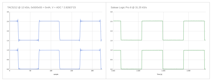
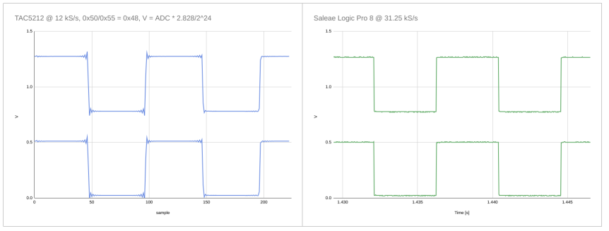
  • Right, just trying to understand the benefits of using incremental mode rather than "normal" mode for DC measurements.  Is the voltage scaling different for incremental mode?  Here is some data comparing TAC5212 ADC output at 12 kHz sampling rate with similar measurements from test equipment.  With register 0x50/0x55 = 0x48, ADC full scale is 1.414 V, and I get good agreement with test equipment by scaling by 2.828/2^24 rather than 0.925*2.828/2^22:

    With 0x50/0x55 = 0x4A, ADC full scale is 2.828 V, and scaling by 2.828/2^23 works:

    Looks like the input voltage level can be accurately read from these measurements, so what capabilities does incremental mode add to the picture?

  • Hi, apologies for the delay I will update thread soon

  • Hi Timothy,

    Can you share the method or script used to measure your input signal alternative to the IADC?

  • HI Daveon,

    I'm using a script written in CircuitPython which you can find at https://github.com/timchinowsky/tac5.  The configure method in tac5.py is where the I2C programming happens.  Here's the key part:

    self.write_reg(0x01, 1, address=a) # Reset all registers to defaults
    time.sleep(0.1)
    self.write_reg(0x02, 9, address=a) # No sleep, DREG and VREF enabled
    if self.width == 32:
        self.write_reg(0x1A, 0x30, address=a) # TDM, 32 bit
    elif self.width ==24:
        self.write_reg(0x1A, 0x20, address=a) # TDM, 24 bit
    elif self.width == 20:
        self.write_reg(0x1A, 0x10, address=a) # TDM, 20 bit
    else:
        self.write_reg(0x1A, 0x00, address=a) # TDM, 16 bit
    self.write_reg(0x78, 0xEE, address=a) # Power up all enabled ADC and DAC channels
    # self.write_reg(0x72, 0x0A, address=a) # disable ADC HPF
    self.write_reg(0x72, 0x8A, address=a) # disable ADC HPF, ultra-low latency decimation filter
    self.write_reg(0x73, 0x0A, address=a) # disable DAC HPF
    self.write_reg(0x1B, 0x40, address=a) # transmit hi-Z for unused cycles

    self.write_reg(0x50, 0x4A, address=a)
    self.write_reg(0x55, 0x4A, address=a)


    self.write_reg(0x55, 0x4A, address=a)

  • Hi Timothy,

    Thanks! So you configured the device as 'normal' but logged voltage digital output and mapped to excel graph? No IADC or diagnostic registers used?

  • Yes, that's right.  So when the datasheet says "TAC5212 supports incremental mode of ADC where analog input channels can be used for DC measurements" but 'normal' mode can also be used for DC measurements, I'm wondering what are the unique features of incremental mode.

  • Hi Timothy, 

    Thanks for the explanation, I've forwarded this thread to our design engineer for this feature to get his feedback.