Other Parts Discussed in Thread: DIX4192,
Tool/software:
Dear Exert
The schematic diagram is as follows: (1. The microphone enters from port A of DIX4192, outputs from port B, and the clock is provided by DIX4192)
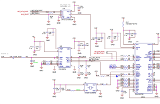
2. The converted digital audio is connected to DIN and then output by SPKP and SPKM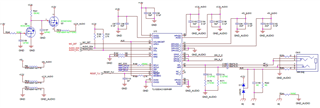
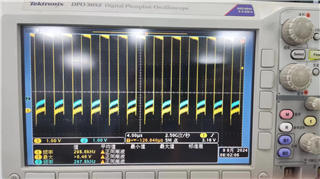
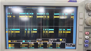
The oscilloscope screenshot is as follows:
MICDATA-RIGHT input signal as shown in the figure
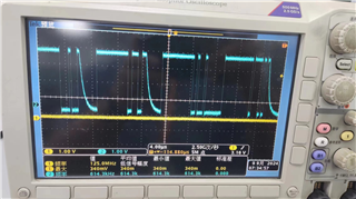
DIX4192: PORT_A_IN, PORT_B_OUT
SPKP and SPKM of TLV320DAC3100