This thread has been locked.

If you have a related question, please click the "Ask a related question" button in the top right corner. The newly created question will be automatically linked to this question.

TPA3255: TPA3255 19pin and 21 pin Error

Part Number: TPA3255

Tool/software:

Dear TI engineers

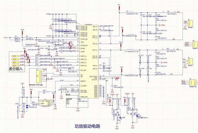
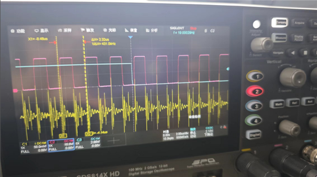
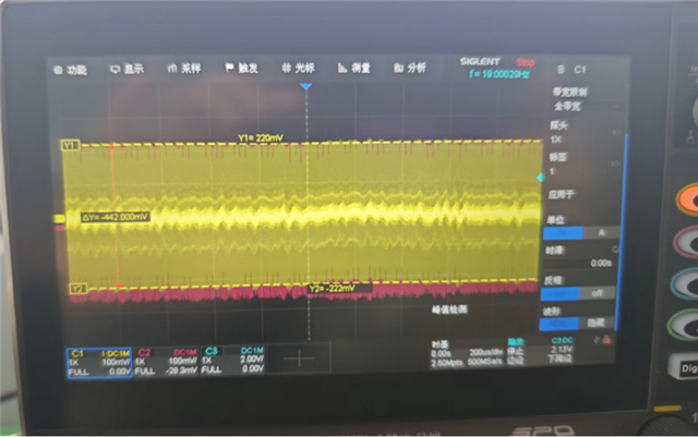
We found a clipping alarm during testing regarding the design of TPA3255. Both pins 19.21 are reporting an alarm.

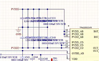
Currently, my settings are 3-pin and 4-pin grounded, and 9-pin and 10 pin open  5, 6, 16, 17 pins open.

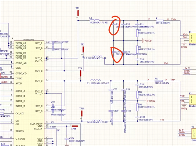
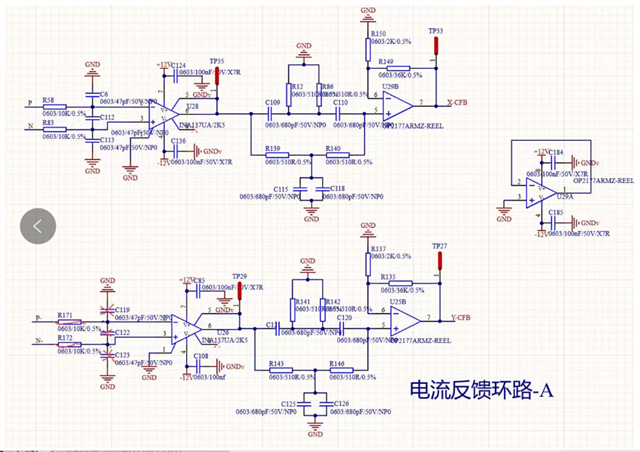
This is my circuit diagram. Could you please help me look at possible causes and how to solve them。

The temperature of the 12V IC for power supply is a bit high, and the temperature of the input electrolytic capacitor is also slightly higher.1000uf 35V used for electrolytic capacitors

  • hi, Li

    1.can you tell me your load resistance value?

    2.can you take a measurement for the current before LC filter?

    3.base on above current value, can you check whether inductor Isat and Itemp have enough margin.

    4.also, can you share the sch more clearly? the cap's spec mixed each other.

    tks

    jesse

  • Hi Jesse,

    Thank you for your reply. The issue mentioned above has now been resolved.

    We just remove the 1uf capacitors in these two places. In addition, the inductance at L1L2 is not soldered and is directly short circuited.

    But we encountered a new problem, how to consider removing the 500kHz oscillation on the current loop?

    Red is the frequency of the D-class amplifier, and yellow is when the signal line on the loop oscillates along with it.

    We added a double-T filter in series to the feedback loop, which only reduced the noise by 50mv.

    This is the schematic diagram. Below, R171 and R172 are short circuited, and the last three capacitors removed.

    TP29 has a red signal as shown in the figure, and TP27 has a yellow signal as shown in the figure.I guess the switching frequency entered the loop from the feedback end.

    Do you have any good suggestions?thanks!

  • Hi Vayne,

    From my understanding, TP29 has the square (PWM) wave and the filter after is used to try and remove the switching frequency. TP27 is then the amplified result of the filtering.

    If this is correct then I suspect the 500kHz is being filtered out, but the harmonics from the square wave nature are not. If you make that "double t" filter into a low pass filter, I suspect that the rest of the harmonics will be removed as well.

    Regards,

    Ramsey