TLV320ADC6140: Daisy Chaining I2S SDOUT/SDIN into GPI/GPO

Part Number: TLV320ADC6140

Tool/software:

Hello there,

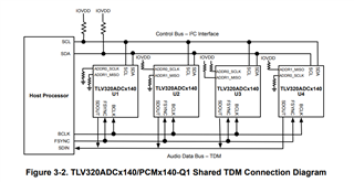
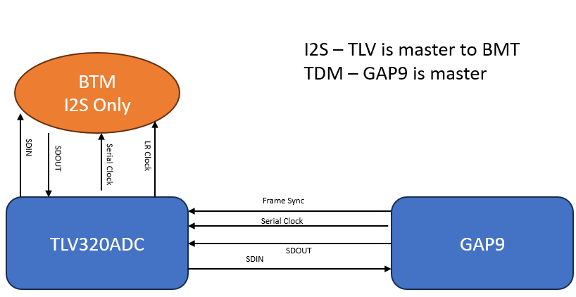
We are using the TLV320ADC6140 to collect 1 analog mic input and 4 PDM microphone streams and output over TDM. We would like to add PCM audio from another device as I2S input/output to the TDM bus using the the free GPI/GPO pins in daisy-chain mode. Is this doable?

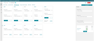
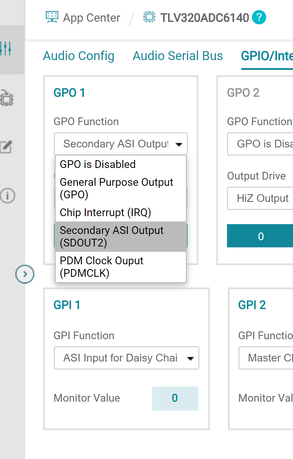
In the PPC3 app for the eval board it looks like I can set GPI to "ASI Input for Daisy Chain - SDIN" and GPO1 to "Secondary ASI Output (SDOUT2)". Is this correct? 

Essentially, my PCM audio device supports I2S but not TDM, so I would like to bring the data lines into the ADC and add it to the TDM bus. Then I would assume that I would simply share the TDM frame clock and bit clock to that PCM audio device directly set to slave mode. Is this how the daisy chain function works?

Thanks so much!

Peter Grinalds

  • Hi Peter,

    Since the PCM audio data you want to share has not already been processed, I believe you want to achieve a Shared TDM bus output as opposed to daisy-chaining. Additionally, ADC6140 can only process 4 channels (4 PDM inputs, or 1 AMIC + 3 PDM inputs) so if an additional channel is needed for recording this would require a second device.

    Shared TDM bus and Daisy-chaining achieve the same goal but the hardware connections are different.

    Daisy chaining is essentially taking post processed digital data of U1 and inserting it onto the TDM line through the GPIO pin on U2. There is a limit on channel insertion with this method. Block diagram of daisy chaining our EVM's shown below:

    Shared TDM bus is explained in

    Multiple TLV320ADCx140/PCMx140-Q1, TLV320ADCx120, and PCMx120-Q1 Devices With Shared TDM and I2C Bus (Rev. C)

    This method connects the DOUT line of all connected devices. Slot configuration is needed so that the audio channels don't conflict and our devices allows up to 4 devices (64 slots) to be configured in this method.

  • Hello Daveon,

    Thank you so much for the reply!

    I want to first correct a statement I made in my original post. I should not have said 4 PDM mic streams. While we do have 4 PDM mics connected, that are only occupying 2 Serial Audio interfaces on the ADC. This leaves 2 other ASIs; one for the analog mic, and one unused for the moment.

    Now regarding TDM, I appreciate the comparison you've made between TDM and Daisy-chaining, but I am still not clear on whether I can take a standard I2S stream and pass it's data line into the GPIO pin (with the register specified for daisy-chaining) such that the ADC adds this audio into one of its TDM frames. Is this possible? I am wanting to use the ADC as a sort of I2S-to-TDM bridge for my bluetooth chipset since it doesn't have a native TDM interface.

    Thank you so much for your help!

    Peter

  • Hi Peter,

    I do think this is possible but before I confirm can you draw out or provide a block diagram of what you're trying to achieve?

  • Hi Daveon,

    Of course, please find below what I am envisioning. I am not sure what clocks the TLV can provide versus what can be passed from the GAP9 MCU, but the datasheet says that the TLV is highly flexible so I am optimistic about that.

    Thanks,

    Peter

  • Hi Peter,

    What your trying to do can be achieved through daisy chain but TLV320ADC cannot be configured to be both master and slave, FSYNC/LRCLK and BCLK will have to be provided from GAP9 to both slave devices.

    You can use one of the unused analog inputs or GPIO pin as a secondary data input for daisy chain. Your GPIO pins can be configured like the example shown below: