This thread has been locked.

If you have a related question, please click the "Ask a related question" button in the top right corner. The newly created question will be automatically linked to this question.

TAC5212EVM-K: PDM Channels Configuration

Part Number: TAC5212EVM-K
Other Parts Discussed in Thread: TAC5212

Tool/software:

Hi,

I try to evaluate the two PDM microphones available on the board (U8 and U7) but w/o sucess up to now.

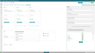
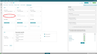
I would like that the TAC5212 generates the PDMCLK on GPO1 and receives the PDMDAT on GPI1.

No clock is observed on GPO1.

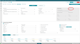
With the scope, I measure: BCLK = 12.288-MHz and FSYNC = 48-kHz.

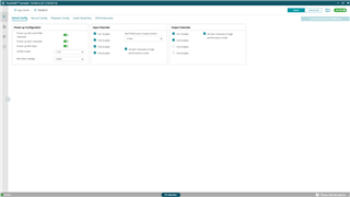
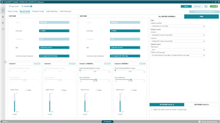
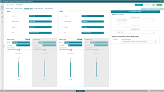
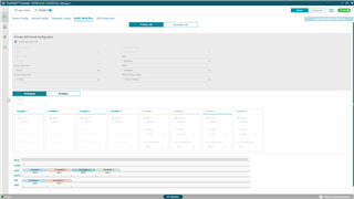
Below some screenshots of my current setting (PPC3).

Thanks in advance for your support.

  • Hi,

    I tried to set the settings you have in PPC and was also not getting PDM clock output on the GPO1. In the EVM user guide, there is a segment of code for an example I2C commands to use a digital PDM microphone. Running this, as well as the line "w a0 0c 40" to set GPO1 as the PDM clock out, gave me a clock of 3.072MHz on GPO1, which is what we expect. See if running this in the I2C Monitor of PPC3 gets a clock out. Don't forget to connect a jumper between the two posts on GPO1 for PDMCLK to get the signal out on the GPO1 test point.

    ##### Record from DMIC Test ######
    # Target Mode, I2S, 32-bit
    # Primary ASI only, multiple of 48KHz Sampling 4x4
    # PDMCLK=GPIO1, PDM Data=GPI1

    w a0 00 00 # Set page 0
    w a0 01 01 # Software Reset
    w a0 02 09 # Wake up with AVDD > 2v and all VDDIO level
    w a0 0a 41 # Configure GPIO1 as PDMCLK with drive active high and low
    w a0 0d 02 # Configure GPI1 as input
    w a0 10 50 # Configure DOUT as Primary ASI (PASI) DOUT
    w a0 13 cc # Configure PDM data on GPI1 with channel 1 data latched on the negative edge and
    channel 2 data latched on the positive edge
    w a0 19 00 # 1 data input and 1 data output for PASI
    w a0 1a 70 # PASI I2S, 32 bit format
    w a0 1e 20 # PASI Ch1 on Left slot 0
    w a0 1f 30 # PASI Ch2 on Right slot 0
    w a0 35 00 # PDM_CLK is 2.8224 MHz or 3.072 MHz
    w a0 76 c0 # Enable input Chl and Ch2, disable output channels
    w a0 78 80 # Power up ADC

    Let me know if you need more help with this.

    Best,
    Mir

  • Hello Mir,

    Thanks a lot for your reply. It really helps me to continue my investigation on this new device.

    If I execute your prodvided I2C commands, I measure a clock of 3.072-MHz on GPIO1. Then, with the command "w a0 0c 41" (and not "w a0 0c 40") I measure the same clock of 3.072-MHz on GPO1.

    After analyzing the differences between my settings and your I2C commands, I found the following issues:

    1. In GPIO/Interrupts, we should first set the Output Drive to "Active Low and Active High" before to set the GPIO Function to PDM Clock Output. Otherwise the Output Drive will be disabled and greyed. Refer to the picture below.

    After Modifying the Outptu Drive from "HiZ Output" to "Active Low and Active High", I measure a clock of about 810-kHz on GPO1 instead of 3.072-MHz.

    2. To try to solve this frequency issue, I focused on register 0x1A (ASI_CFG1). Reading back this register, give me 0x00 but 0x30 was expected because Word Length is set to 32-bits in Audio Serial Bus tab. Updating the register to 0x30 does not solve the frequency issue. Is 0x00 or 0x30 expected when Word Lenght is set to 32-bits?

    3. Your I2C commands set the register 0x1F (PASI_TX_CH2_CFG) to 0x30, thus set the bit 6 to 1. According to the datahseet, the bit 6 is a reserved read only bit. Is it a datasheet or a command error?

    Finally, I played with different Audio Serial Bus settings (TDM, I2S, 32bits, 16bits...) but w/o success. Maybe it is a PLL configuration issue: this last is set to "Enable Auto Clock Cfgn". What do you think? Are you able to reproduce this behavior?

  • Finally I found the error: for an obscure reason, in Audio Serial Bus tab in Advanced Mode, BCLK/FSYNC Ratio was set to 8. Modifying this value to 0 solves the frequency problem.

    Again thank you for your support.

    BR,

    Sebastien

  • Hi,

    Running the script should be all you need to do. PPC3 has a bug where if you run a script, it does not update the GUI, so if you ran the script and then started changing the parameters in the GUI, you may have discovered some other issues and then ended up in the same place you started. We have a new version coming out soon that will fix some of these issues, but if you want to see what the script does to the device, a way to get the GUI to update is to run the script, then keep the device plugged in but back out of the TAC5212 GUI and go to the App Center, then re-open the TAC5212 GUI and select to update GUI with device values. That should show you what the script does! And you are probably right about the Hi-Z output being incorrect, sorry about that. I have the new version of PPC so my hi-Z/active low active high settings are a little different in the GUI. The BCLK-FSYNC ratio settings are also different in my PPC - I can't edit that at all since I am not in controller mode. Glad you got it sorted.

    Best,
    Mir