This thread has been locked.

If you have a related question, please click the "Ask a related question" button in the top right corner. The newly created question will be automatically linked to this question.

Need to reduce/eliminate ticks and pops sound on PGA2500 when changing gain from minimum to maximum

Other Parts Discussed in Thread: PGA2500, PGA2500EVM

We have been having problems with the PGA 2500 creating ticks and pops when changing the gain from minimum to maximum. This is more apparent when there is no input plugged into the mic input, and when listening at louder monitoring levels.  It seems that a majority of this is caused by leakage mismatches between the input protection diodes (MBRA120), which results in a positive or negative offset at the input junctions, depending on the amount of the leakage by each diode. Obviously, some channels pop worse than others, through the random variations of these diodes.

Removing the diodes eliminates or greatly minimizes this popping, as does replacing the leakier Schottky types with a low leakage silicon diode.

We realize that this can place the inputs somewhat past the maximum input design ratings (especially during application of Phantom Power), so we’re looking for input from TI as to whether this is a workable solution, or if there are any alternative suggestions.


The Zero crossing function has little if any effect on reducing this behavior. In fact with it enabled, we’ve seen intermittent behavior where advancing the gain rapidly from minimum to maximum gain with no input signal will cause a delay in the actual gain change of up to 4 or more seconds. Disabling the Zero Crossing detector restores normal gain tracking in these situations.

  • Hello Jimmy,

    Using the PGA2500 on the bench or EVM board, I am able to hear a low level "pop" when a very big change in volume is made in a single step.  For example going from 10dB to 60dB, a low level pop can be heard when monitoring the sound at high levels.    I am not able to hear the pop sound when the volume is gradually changed between level to level; or smaller steps in the gain are made.

    The gain of the PGA2500 is digitally controlled; so when the gain is changed in a single very big step; the DC input offset of the amplifier is also gained producing a low level pop.  The DC servo loop helps minimize the output offset voltage; but it takes a finite time to compensate for the offset. The settling time of the DC servo loop is a function of the  DC servo capacitors.  If the gain change is made gradually, or in smaller steps, no pop is noticeable.  You are correct that the zero-crossing signal is not related to the "pop" sound; the low level pop sound experienced is probably due to the DC offset of the device being gained up considerably (50dB) when a instantaneous gain is made.  The way to avoid this behaviour is to ramp the volume in smaller steps.

    The zero crossing function minimizes audible artifacts when a signal is present; detecting the zero crossing and then changing the volume; limiting the glitch in the sound signal that occurs when changing gains.   The internal zero-crossing allows the volume to change whenever the differential input signal is very close to zero.  For no signal, or signals below approximately 2mVp-p (approximately) or -60dBu (approximately); the device changes the gain immediately.  The zero-crossing function will timeout and change gain after ~16ms if no zero crossing was ever detected.  I have not been able to reproduce a situation where the gain change takes longer than this ~16ms delay.  How did you determine that the gain change is taking 4 seconds?  Is the circuit used at the input of the PGA2500 the same as the one shown on the PGA2500EVM?  

    Please see an oscilloscope plot showing the ~50mV glitch on the PGA output after a big step gain change (10dB to 60dB).  The "glitch" signal that I am able to reproduce on the output is in the order of ~50mV.   How large is the output glitch that is observed on your side?

    Best Regards,

    Luis


  • Hi Luis,

    What we would really like to know is if using silicon diodes as the protection diodes on the input of the PGA2500 is permissible?


    We have prototyped several systems using the Fairchild S1J diodes, which are a low leakage silicon diode. This solves the popping problems we have been experiencing from the use of the MBRA120 schottky diodes. I am enclosing the data sheet for the S1J.  Similar diodes are also manufactured by Diodes Inc and others.


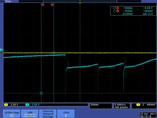
    I’m also sending some screenshots of the voltage transients recorded at each input of the PGA2500 when each input is shorted to ground while the 48V phantom supply is activated. As you can see, the transients can reach -8 volts in some instances, which is beyond the specified maximum input.

    We have applied (>200) multiple shorts to the inputs of the amps and have not experienced any failures or degradation of performance in our testing so far.


  • Hello Jimmy,

    When the PGA2500 was in development, the schottky diode protection scheme was a typical protection scheme used at the time.  There may be other protection schemes that may be used, however,  the user must ensure that the maximum allowed absolute ratings for the PGA2500 device inputs and supplies are not exceeded.  The inputs must not exceed +/-0.3V above the VA supply as specified on the datasheet.  

    Attached is an article available on the web on different protection schemes that you may find helpful (Bortoni and Kirkwood:  The 48V Phantom Menace Returns).  On figure 17, the authors of the article show a protection scheme using 4x 1N4004GP diodes.  A possible scheme could be to use the 4x 1N4004GP protection diodes with 47Ohm series resistors. 

    Best Regards,

    Luis

  • Luis -

    Thanks for the link and reference to Rosalfonso's and my AES article.

    Wayne Kirkwood