OPA1632: Output does not exist in differential input and differential output configuration

Part Number: OPA1632
Other Parts Discussed in Thread: OPA1633, OPA1622

Tool/software:

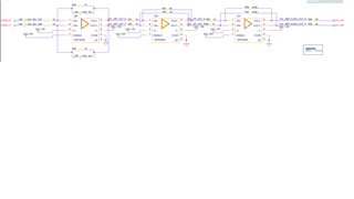
The circuit of OPA1632 is as shown in the attached schematic.

Right now, we have mounted only the first stage, U29 and its circuit. The capacitors C94 to C97 are removed. R46 to R49 are mounted with 220 ohm resistors. Input of 1kHz Sine tone, 500 mV to 1V is fed at the resistors R47 and R48 from an audio analyzer. The output is measured by an audio analyzer at the pads of R51 and R50 (R51 and R50 are not mounted right now). The output is expected to be Sine tone but it is nothing.

When I carried out simulation using TINA TI the output is as expected.

Please let me know the changes required to be made in the circuit if any.
  • Hello Shreeprada,

    Can you confirm your OPA1632 IC is powered on and drawing current which is close to the Iq (quiescent current) specification?  For the OPA1632 the Iq is 13mA.

    You may also want to check your enable signal, so that you are not providing a voltage which puts the OPA1632 into power down.

    As a small note, we do now have the OPA1633 available if you find the improved specifications are good for your design.  It is the same package and pinout, being pin-to-pin (p2p) compatible.

    Best,

    Alec

  • Hi Alec,

    When OPA1632 IC is powered on, it is drawing 40mA current (20mA on V+ rail and 20mA on V- rail).

    The Enable signal is 3.3V.

    Please share the samples of OPA1633 for our evaluation. But we will take it up after the issue with OPA1632 is resolved.

    Is there any check to verify if the IC is good?

    Regards,

    Shreeprada

  • Hello Shreeprada,

    You should be able to request samples from ti.com off of OPA1633 webpage.  Please let me know if you are unable to do so.

    Regarding the OPA1632 circuit, the typical Iq is 13mA.  You can check if your Iq aligns with the typical; you should not be seeing an Iq measurement which is far off from this value.  The maximum Iq is 17.1mA.

    If you are drawing 20mA of Iq, your device may be damaged or may be sourcing more current than it needs to function. 

    Can you verify your schematic matches your PCB?

    Can you measure Iq with an ammeter and confirm the supply voltages and Iq values?

    Can you try putting an 800 Ohm differential load across the outputs of the OPA1632? Does this change your Iq measurement?

    Best,

    Alec

  • Hi Alec,

    Yeah, the schematic matches the PCB.

    The supply voltages on V+ and V- are 5V and -5V respectively. Should I connect 800 ohm only across the differential output lines? Is any nearby value fine?

    Can I continue having the series resistances at the differential output at 1kohm?

    Regards,

    Shreeprada M S 

  • Hello Shreeprada,

    For this test of the IC, you can put a higher resistance across differential output lines, such as 800 Ohms, 600 Ohms, 400 Ohms, etc.

    Based on the schematic and your first message, I did not think R50 & R51 (series output resistors) were populated?

    I am not making a recommendation to add 800 Ohms differential to your production board permanently, I am asking you do so for debugging so I can better understand why the device is drawing more current than it should be drawing at rest.

    Is your current measurement taking with OPA1632 powered on with no signal, or taken with an input signal present at the amplifier?

    Best,

    Alec

  • Hi Alec,

    Following is the observation:

    The current drawn on each of positive and negative supply voltage rail is 20mA .

    Following is the circuit condition:

    Series output resistors (R50 and R51): Not mounted

    Resistor across differential output lines: 800 ohm

    input and output audio signal: Not connected

    Positive and Negative supply voltage values: +5V, -5V

    What else can I try please let me know.

    Regards,

    Shreeprada M S

  • Hello Shreeprada,

    I can work on evaluating the OPA1632 next week in the lab to see what measurements I can obtain.  

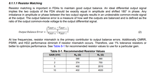
    You can also try following the recommended resistor value for RF and RG, found in the datasheet on p. 14:

    RF=RG=390 Ohms for Gain of 1V/V.  I would also recommend taking an Iq measurement with R50 & R51 connected.

    Best,

    Alec

  • Hello Alec,

    The values of RF and RG suggested in the datasheet are already tried and found no difference in the output.

    I have also tried with R50 and R51 mounted but without any change in the output.


    Regards,

    Shreeprada M S

  • Hello Shreeprada,

    Okay, thank you.  I have devices now at my desk, I also need time to build an EVM to examine in the lab.  I will provide an update by the end of the week.

    Best,

    Alec

  • Hello Alec,

    Any updates on this issue? Could you check the circuit with the eval board?

    Regards,

    Shreeprada M S

  • Hello Shreeprada,

    I have not yet been able to take the device into the lab.

    As I am preparing to do so, can you share any key tests or measurements you would like me to examine for you?

    Best,

    Alec

  • Hello Alec,

    Please check the output of the IC for 1kHz, 50mV sine wave input with the circuit shared before.

    Regards,

    Shreeprada M S

  • Hello Shreeprada,

    Thank you for sharing your input signal request.  I am assembling a board compatible with the OPA1632.

    I expect to make measurements next week.

    Best,

    Alec

  • Hi Alec,

    Any updates regarding the issue?

    Regards,

    Shreeprada M S

  • Hello Shreeprada,

    I have an EVM and I will be testing the OPA1633 tomorrow for other support.  I can use the same EVM to also test the OPA1632 tomorrow or Friday.

    Best,

    Alec

  • Hello Shreeprada,

    I observe output on my EVM in the lab.  Could you probe and check if your input signal is present at R47 & R48, and also check if the signal is present at the inputs to the OPA1622 pins 1 & 8.

    Please also check your probe/oscilloscope attenuation and make sure you are not measuring the outputs incorrectly.  You should see an output signal of some voltage level if the input is receiving a signal.

    Best,

    Alec

  • Hi Alec,

    The issue in the circuit is resolved. The problem was, in the circuit the connections to vout+ and vout- were interchanged.

    Thanks for the support.

    Regards,

    Shreeprada M S