TAS5827: Why does THD+N increase dramatically over a certain range of inputs?

Part Number: TAS5827

Tool/software:

Hi TI Team,

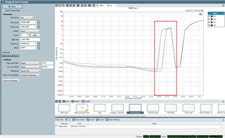
When I was testing, I found that with the increase of the input signal(I2S Input), the output distortion(THD+N) will increase sharply in a certain input range, continue to increase the input signal, and the distortion will return to the normal range. 

I would like to ask TI what may be the reason for this abnormal situation.

Thanks.

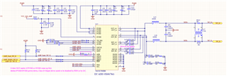
Here is my schematic and the data from my tests.

PVDD: 26V

A/GVDD: 5.5V

I2S input from AP585

Load: NO Load.

Schematic
THD+N VS INPUT
RMS VS INPUT
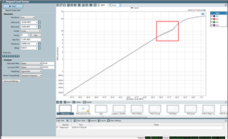
GAIN VS INPUT
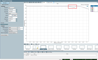
-18dBFS input THD+N
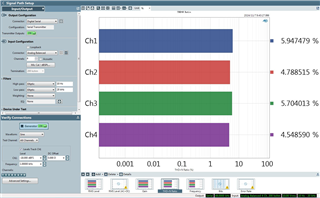
-13dBFS THD+N
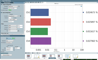
-20dBFS THD+N
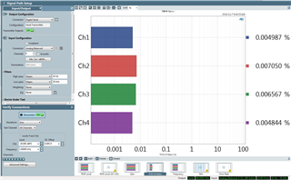
  • hi, 

    can you share me the spec of inductor?

    also, the ppc3 config file. what is the filter you use for these test?

    thank you very much for your data.

    can you also check the fft at those thd worse area? 

    tks

    jesse

  • hi Jesse,

    I tested it with TI's 5827EVK board and got the same results.

    I found this to be related to PVDD, which doesn't happen at 18V, but it does happen at 24V and 26V.

    Both BD mode and HYBIRD will have similar phenomenon.

    Here is test conditions:

    PVDD: 18/24/26V

    Input: AP AUX IN(1mV-2V sinewave)

    Load: 16ohm Dummy Load.

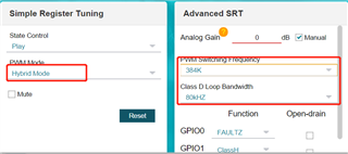
    Mode: BTL/BASE PRO 48K/PLAY/HYBIRD

    PWM FREQ: 384K

    If you can, please try it. Thanks.

    Also, I found that after selecting LITE mode, the following HYBIRD mode BD mode have same PWM duty cycle.