Because of the Thanksgiving holiday in the U.S., TI E2E™ design support forum responses may be delayed from November 25 through December 2. Thank you for your patience.

TLV320DAC3101: Power Rails and Startup Sequence

Part Number: TLV320DAC3101
Other Parts Discussed in Thread: LM3880

Tool/software:

Hi there,

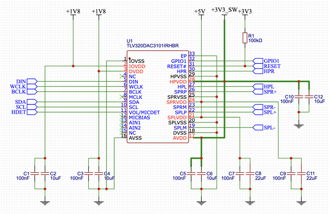
we're planning to use the TLV320DAC3101 in a home entertainment device. To get a better understanding of powering and power up sequence we're in progress creating a test PCB which interfaces with an ESP32S3. Main power has to be 3.3V, so we added a booster to 5V. Attached the schematics so far.

Questions:

#1 Is the step by step power up sequence mandatory? What would be the disadvantage to power up all at once? (we need to enable the chip fast)

#2 Would it be safe to power up at least IOVDD and DVDD at once? (want to keep things simple and use the LM3880 which only offer 3 flags)

#3 IOVDD: any disadvantages to power it with 1.8V? According to the specs it would just be a bit slower than using 3.3V, right?

#4 How fast could we go with the startup sequence? Would the 10ms delay version of the LM3880 be sufficient?

Any other caveats I have not thought of in my design? I'm no electronics pro by any means, but I hope the schematics are not totally rediculous.

TIA,

Jörg

Schematic_TLV320DAC3101_Test_2024-11-07.pdf

  • Hi Jorg,

    The power supply recommendation states that It is important to consider that the digital activity must be separated from the analog and speaker activity. Also the recommended power sequence is: 1. Speaker supplies 2. Digital supplies 3. Analog supplies. Following this order, assures the correct internal set up  or resetting the registers or ....

    Some devices  might get damaged for not following the correct sequence ( usually it says requirement , instead of  recommendation) 

    I believe it is ok to power IOVDD and DVDD together, just keep in mind IOVDD has a wider range of operation

    Using 1.8V is slower but specs of the DAC itself stay the same .I am not familiar with LM devices but I  believe 10ms is ample enough 

    Your schematic is not completely connected, for example several grounds are not connected or supply pins  are connected to caps but not connected to actual supply.  You can always use the schematic in user's guide as a reference or starting point. 

    Users Guide

    Regards,

    Arash

  • Hi Arash,

    thanks for your swift reply! I will keep my setup for now and add an option to skip the sequencer to compare results.

    Could you give please me an example of which ground or supply is not connected? I could not find any missing connections. Example 3.3V:

    Thanks again,

    Jörg

  • Jorg,  many of your connections are missing in your first attachment ( or at least when i open it at my end) , The above schematic  is ok,

    Regards,

    Arash

    Regards,

    Arash 

  • Ah, glad it was only a display issue. Seems the PDF exporter is rubbish.