This thread has been locked.

If you have a related question, please click the "Ask a related question" button in the top right corner. The newly created question will be automatically linked to this question.

TLV320ADC3140: Resolution Jump and Output Nonlinearity in ADC with Differential Sine Wave Input

Part Number: TLV320ADC3140


Tool/software:

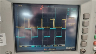
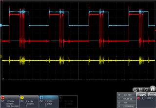
I am facing an issue where the expected resolution is not achieved when inputting a sine wave to the ADC. I would like some advice on this.

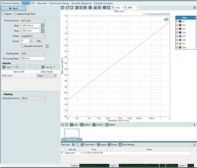
I have a major issue with my ADC design. Non-linearity check: There are large jumps in the output, particularly with the issue where the MSB 4 bits show only 0b0000 or 0b1111.Please advise.

  • Operating Mode: Slave mode

  • Power Supply Voltage: 3.3V

  • Input type : Differential input full-scale AC signal voltage

  • Output Length: 24-bit

  • Data Format: Left-justified (LJ)

  • Polarity: Unipolar

  • Reference Voltage (Vref): 2.75V

# Differential 1-channel : INP1/INM1 - Ch1
# FSYNC = 96 kHz (Output Data Sample Rate), BCLK = 6 MHz (BCLK/FSYNC = 64)
################################################################
#
#
# Power up IOVDD and AVDD power supplies keeping SHDNZ pin voltage LOW
# Wait for IOVDD and AVDD power supplies to settle to steady state operating voltage range.
# Release SHDNZ to HIGH.
# Wait for 1ms.
#
# Wake-up device by I2C write into P0_R2 using internal AREG
w 98 02 81
#
# set LJ-Mode, 24 bits word length
w 98 07 A0
#
# Enable Line input, Typical 10-kΩ input impedance
w 98 3C 84
#
# Enable Input Ch-1  I2C write into P0_R115
w 98 73 80
#
# Enable ASI Output Ch-1 to Ch-4 slots by I2C write into P0_R116
w 98 74 80
#
# Power-up ADC and PLL by I2C write into P0_R117
w 98 75 60
#
# Apply FSYNC = 96 kHz kHz and BCLK = 6 MHz MHz and
# Start recording data by host on ASI bus with LJ protocol 24-bits channel wordlength
  • Hi Hattori-san,

    Could you demonstrate the non-linearity you are seeing? Could you possibly take a graph of Vrms input vs FS output?

    Thanks,
    Jeff McPherson

  • Thanks Mr Jeff,

    I have prepared a graph showing the non-linearity issue based on your suggestion, plotting Vrms input against

    1 : A plot of resolution: vertical axis represents 24-bit resolution, please disregard the numbers on the horizontal axis

    2 : Vrms input:±500mV sin wave (CH1:IN1M_GPO1, CH2:IN1P_GPI1)

    Vrms input(CH1:IN1M_GPO1, CH2:IN1P_GPI1)

    3: FS output(CH1:SDOUT, CH2: FSYNC(96kHz))

    You can see the top 4 bits jumping.

  • Hi Hattori-san,

    The graph does not mean much if I do not know the horizontal axis.

    I ran your script on an EVM and plotted the analog input vs digital output and it is linear so I don't think this is a software issue. I think it's related to how you are measuring the data.

    Also I do not recommend trying to interpret the data by watching the bits. The data is two complement so it will not count up and down like you might expect. My data has bits that jump around in a similar manner but I can see that the data is showing up fine after being analyzed.

    Best regards,
    Jeff McPherson

  • Thank you very much for your kind and detailed response. I realize now that I made a mistake regarding the data format. It is clear that the issue lies in the way I am measuring the data.

    I understand that the digital output signal is being output as two complement.

    capture:+500mV sin wave (CH1:SDOUT, CH2: +500mV sin wave, CH3: FSYNC(96kHz))

    capture:-500mV sin wave (CH1:SDOUT, CH2: -500mV sin wave, CH3: FSYNC(96kHz))

    As can be seen from the capture, when a ±500mV sine wave is input, the resolution is distributed from 0xFFFFFE (-500mV) to 0x000001 (+500mV).

    I understand that attempting to interpret the data by simply looking at the bits is a foolish approach, but I would appreciate any advice you may have.

  • Hi Hattori,

    I recommend investing in some kind of digital serial analyzer that can support I2S/TDM audio formats. That will give you the easiest time when debugging. But I think you have shown that that you are getting expected values.

    Best regards,
    Jeff McPherson

  • I have an additional question. The datasheet specifies that the output is PCM. Does this refer to Linear PCM? The data format I am examining appears to be DPCM.

  • Hi Hattori,

    It is a linear PCM. Each data word is a fixed bit width that contains the two's complement value of the particular sample. 

    Best regards,
    Jeff McPherson