This thread has been locked.

If you have a related question, please click the "Ask a related question" button in the top right corner. The newly created question will be automatically linked to this question.

TAD5242: Pseudo-differential Output to headphone directly way

Part Number: TAD5242
Other Parts Discussed in Thread: TAD5212

Tool/software:

Hi team,

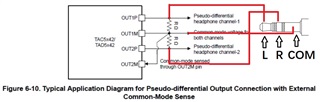
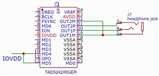
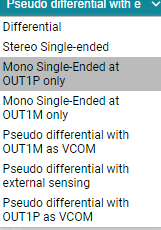
According to datasheet, TAD5242 can set to Pseudo-differential Output mode to drive 16 or 32Ohm headphone directly. But it just exhibited a schematic diagram in Figure 6-10. I am not quite understanding what does "External Common-Mode Sense" means. For my understanding, OUT1M works as Common mode voltage output and OUT2M as Common-mode sense input? I use red line to connect the headphone plug as showed in attached pic. Is it correct or not? Can you provide more details about "Pseudo-differential Output to headphone" connection way? And a real example of schematic is preferred.  Thanks.

  • Hi,

    From what I understand, pseudo-differential signals are like a version of a single ended signal but with a common mode applied to both P and M sides of the signal. This can be useful for some headphones that only support a voltage range above 0, for example. The external common mode sense example schematic would be used if the sleeve of the jack already had a bias or common mode applied. In this case, the OUT2M pin would be used to measure the common mode, and the resistors placed would pull up the outputs to that common mode. If you add in a pull up resistor and connect the point at OUT1M to OUT2M, this should work for this setting. If your jack does not already have a bias voltage, you can use the preexisting common mode applied on the outputs as specified in the "DAC channel OTHER PARAMETERS" section of the datasheet, 0.9V or 1.65V depending on your AVDD.

    What are your headphone specs? Let me know any more info about your setup so I can help more.

    Best,
    Mir

  • Thanks for your fast response. The headphone is just a normal one with "L-R-Ground(or common)" plug. No external bias voltage on the plug sleeve. Please check if below understanding is correct: under Pseudo-differential Output mode(MD4&5 both set high), only OUT1P&2P pin will output signals (with half AVDD common voltage bias) and OUT1M&2M just output constant common voltage(such as 1.65V when AVDD=3.3V). So the OUT1M&2M can be tied together as the common terminal and then connect to the GROUND(or COMMON) sleeve of headphone plug as I show in below pic. No extra R needed to pull up the M pins. But I don't understand what "External Common-Mode Sense" means? As you mentioned, if "the preexisting common mode voltage applied on the outputs" 1.65V can be used in this case then no external common mode voltage needed any more? Thanks

  • Hi Kevin, sorry about the delay, I will answer tomorrow.

  • Hi,

    I heard back from our systems expert about this. The pseudo differential mode requires the common mode to be applied externally if you want to apply your own common mode output, so this is what external common-mode sense is. Most likely, all the outputs have the default common mode voltage applied just as you described if there is no external voltage applied to the external common mode sense pin. I can verify this in the lab on Monday if you want. Your headphone jack connection looks to be correct!

    Best,
    Mir

  • Yes that would be great if you can verify this in lab.  Pls update me if any result. Thanks.

  • Hi Kevin,

    After doing some testing and discussion, we realized I was wrong about pseudo differential mode - it does NOT require an externally-applied common mode, instead it serves to generate the common mode voltage on the M output. While single ended mode outputs the signal on the P output and ground on the M, pseudo differential mode outputs the signal on the P output and the common mode on the M. Both single ended and pseudo differential outputs have a common mode of 1.65V for a 3.3V AVDD. So, in pseudo differential mode, the common mode that is output is 1.65V - you do not apply an external bias to generate this output. There are three "types" of pseudo differential output you can select, here they are in PPC:

    The pseudo differential with OUT1M as VCOM is what I described, VCOM (1.65V or other common mode for lower AVDD) is output on OUT1M instead of ground as in a single ended output. Pseudo differential with OUT1P as VCOM switches the outputs as described. Pseudo differential with external sensing is the one we were confused about - but this "external" sensing is not an externally applied voltage, instead it is describing how the OUT1M and OUT2M need to be shorted together for the common mode output to be the exact same between the two. This is useful for stereo headphones that need the sleeve to be a common mode (positive voltage) and not ground as in a stereo single ended configuration. If the OUT1M and OUT2M are shorted, as shown in the diagram in the datasheet that you attached at first, then that is the external part, and there is an internal feedback loop that makes sure these output common mode voltages are the same.

    So, for your application, it comes down to if you need your sleeve on the headphone jack to be a positive voltage or ground. If ground, then do stereo single ended headphone drive, and if you need the common mode output for your headphones, then select the pseudo differential with external sensing mode with headphone drive. For both setups, you would want OUT1M and OUT2M to be connected to the sleeve of the jack, the only difference is what voltage level they are outputting.

    I hope this makes sense and let me know if you have any more questions.

    Best,
    Mir

  • Hi Mir,

    Your testing and answers are really helpful~  

    Thanks

    BR//Kevin

  • Hello Mir,

    I had exactly the same question as Kevin, your answer gives more details but image in the answer confuses a lot!

    TAD5242 is hardware/pin configurable and, according to the datasheet, MD4 and MD5 must be set HIGH to set "Pseudo differential output with external common-mode sense; Headphone load only" output mode. Also, mono output can be selected by setting MD6 HIGH.

    1. I wonder how you configure:

    Pseudo differential with OUT1M as VCOM

    - Pseudo differential with OUT1P as VCOM

    I worry there are no extra MDx pins for that config...

    2. If I read the image from your answer correctly, "Pseudo differential output" is not compatible with MONO output, MONO is always single-ended. I am I right?

    Thank you in advance!

    Regards

    S

  • Hi Sergey!

    Sorry about the confusion. I was doing testing on a software-controlled device, the TAD5212. It is the software-controlled version of the TAD5242, a hardware controlled DAC. In the software controlled devices, we can choose those options in my screenshot, they are in the PPC3 software as output settings.  On the TAD5242, only the "external common mode sense" mode is able to be enabled (via pins MD4 and 5), this ensures the same common mode is used for both OUT1M and OUT2M through an external connection.

    For the software controlled devices in this family, we can set each output (OUT1 and OUT2) to different drive modes - so for example, we could do OUT1 is pseudo differential with OUT1M as VCOM and OUT2 is single ended. The hardware controlled device can be set to only one mode for both outputs so there is no need for varying versions of pseudo differential mode. If you want to use only one channel with pseudo differential mode, you don't need to connect anything to OUT2P or OUT2M and it will work the same as if it was in "Pseudo differential with OUT1M as VCOM" mode.

    Also, the mono vs stereo in this picture is confusing if you have not used PPC - "stereo single ended" means it sets both OUT1P and OUT1M to both single ended signals, which you can reference to ground on the board without using the OUT1M output as the ground or reference. Other than this mode, which again is a software-controlled only feature, all other output modes will output one channel per output pair of pins (OUTxP+M) - the only thing differing is the reference level output on the M pin between single ended, pseudo differential, and then differential is referenced to an inverted version of the signal.

    Let me know if you have more questions.

    Best,
    Mir