Tool/software:
Hello,
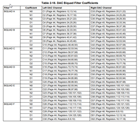
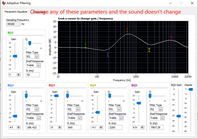
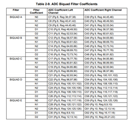
I use IN2 to route to the left channel, IN3 to the right channel, HPL to do the left channel, HPR to do the right channel, and also need to output the audio output from MCU through I2S. I experimented in EVM and found that it can't adjust EQ (adaptive filtering). Why is that and how do I need to change it to debug EQ? Here is my register configuration. I found that D4 of P0_R29 can adjust EQ, but the sound of MCU is gone. Please help me solve this problem, thank you!
regards.
###############################################
# Software Reset
###############################################
#
# Select Page 0
w 30 00 00
#
# Initialize the device through software reset
w 30 01 01
#
###############################################

###############################################
# Clock Settings
# ---------------------------------------------
#The input clock signal : MCLK = 11.2896 MHz,BLCK = 1.4 MHz, WCLK = 44.1 kHz
###############################################
#
# Select Page 0
w 30 00 00
#
# NADC = 1, MADC = 2
w 30 12 81 82
#
###############################################

###############################################
#AGC
###############################################
w 30 00 00
w 30 57 7E
w 30 56 80
w 30 58 56
w 30 59 12
w 30 5A 33
w 30 5B 18
w 30 5C 06

w 30 5F 7E
w 30 5E 80
w 30 60 56
w 30 61 12
w 30 62 33
w 30 63 18
w 30 64 06
###############################################

###############################################
# Enable Loopback Page 0 register 29
###############################################
#
# Loopback enable for stereo audio data
#w 30 1D 10
#
###############################################

###############################################
# Signal Processing Settings
###############################################
#
# Select Page 0
w 30 00 00
#
w 30 14 40
# Set the ADC Mode to PRB_R7
w 30 3d 07
#
###############################################

###############################################
# Initialize Codec
###############################################
#
# Select Page 1
w 30 00 01
#
# Disable weak AVDD in presence of external
# AVDD supply
w 30 01 08
#
# Enable Master Analog Power Control
w 30 02 00
#
w 30 0a 40
# Select ADC PTM_R4
w 30 3d 00
#
# Set the input powerup time to 3.1ms (for ADC)
w 30 47 32
#
# Set the REF charging time to 40ms
w 30 7b 01
#
###############################################

###############################################
# Recording Setup
###############################################
#
# Select Page 1
w 30 00 01

#MICBIAS
w 30 33 50

# Route IN2L to LEFT_PGA_P with 20K input impedance
w 30 34 20
# Route IN2R to LEFT_PGA_N with 20K input impedance
w 30 36 20
# Route IN3R to Right_PGA_N with 20K input impedance
w 30 37 08
# Route IN3L to Right_PGA_P with 20K input impedance
w 30 39 08
#
# Unmute Left MICPGA, Gain selection of 6dB to make channel gain 0dB
# Register of 6dB with input impedance of 20K => Channel Gain of 0dB
w 30 3b 00
#
# Unmute Right MICPGA, Gain selection of 6dB to make channel gain 0dB
# Register of 6dB with input impedance of 20K => Channel Gain of 0dB
w 30 3c 00
#
# Select Page 0
w 30 00 00
#
# Power up LADC/RADC
w 30 51 c0
#
# Unmute LADC/RADC
w 30 52 00
#
###############################################

###############################################
# High Performance Stereo Playback
# ---------------------------------------------
# PowerTune mode PTM_P3 is used for high
# performance 16-bit audio. For PTM_P4,
# an external audio interface that provides
# 20-bit audio is required.
#
# For normal USB Audio, no hardware change
# is required.
#
# If using an external interface, SW2.4 and
# SW2.5 of the USB-ModEVM must be set to
# HI and clocks can be connected to J14 of
# the USB-ModEVM.
#
# Audio is routed to both headphone and
# line outputs.
###############################################

###############################################
# Clock Settings
# ---------------------------------------------
# The input clock signal : MCLK = 11.2896 MHz,BLCK = 1.4 MHz, WCLK = 44.1 kHz: MCLK = 11.2896 MHz,
###############################################
#
# Select Page 0
w 30 00 00
#
# NDAC = 1, MDAC = 2
w 30 0b 81 82
#
###############################################

###############################################
# Signal Processing Settings
###############################################
#
# Select Page 0
# w 30 00 00
#
# Set the DAC Mode to PRB_P8
w 30 3c 08
#
###############################################

###############################################
# Playback Setup
###############################################
#
# Select Page 1
w 30 00 01
#
# De-pop
w 30 14 16
#
# Route LDAC to HPL/HPR
w 30 0c 0a 0a
#
# Route RDAC to LOL/LOR
#w 30 0e 0a 0a
#
# Power up HPL/HPR and LOL/LOR drivers
w 30 09 33
#
# Unmute HPL/HPR driver, 0dB Gain
w 30 10 04 04
#
# Unmute LOL/LOR driver, 0dB Gain
w 30 12 00 00
#
# Select Page 0
w 30 00 00
#
# DAC => 0dB
#w 30 41 00 00
# DRC
w 30 41 0A 0A
w 30 44 73
w 30 45 00
w 30 46 B6
#
#
# Power up LDAC/RDAC
w 30 3f d6
#
# Unmute LDAC/RDAC
w 30 40 00
#
###############################################