


Tool/software:
I connected a microphone to MIC0RP. I want to transmit this microphone via bluetooth with i2s by passing it through the ADC. I made the necessary register settings in the block diagram. I wrote 01 to the d7-d6 bits in the P1/49 register, meaning "CM is selected for the MIC PGA with feed-forward resistance RIN = 10 kΩ."
I wrote 01 to the d5-d4 bits in the P1/48 register, meaning "MIC1RP is selected for the MIC PGA with feed-forward resistance RIN = 10 kΩ"
My mic gain in the P1/47 register is 14.5 dB.
After these settings, don't I need to read the data coming from the microphone when I read with an oscilloscope on the dout pin of the codec? I tried and verified that the microphone works with the analog bypass. I have now turned off the analog bypass. When I read from Dout with an oscilloscope, there is a continuous data but it does not change according to the movement in the microphone. Do I have a mistake on the I2S side (frequency, sample rate settings) or am I missing a setting that I should have set beforehand?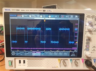
blue signal is TLV320AIC3100 dout pin
purple signal is din pin, din pin is working properly. When i send music or voice signal, purple signal changes. Now i send no signal so it's normal.
