This thread has been locked.

If you have a related question, please click the "Ask a related question" button in the top right corner. The newly created question will be automatically linked to this question.

TPA3220: Tpa3220 Error entering PBTL mode (Urgent , could you reply today?)

Part Number: TPA3220

Tool/software:

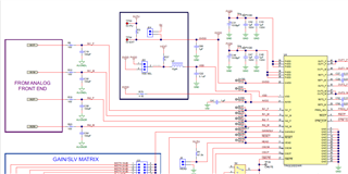
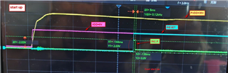
We design TPA3220 work on BTL mode(SCH as below) , but each day first time power up , TPA3220 go into PBTL mode,  retry power up again , TPA3220 go into BTL mode .

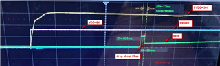
If the machine is turned off for more than 1 hour, restarting will enter PBTL mode.

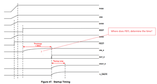
We try to change C39/40 from 22uf to 1uF , the error entering PBTL mode remove. I am not sure this solution work or not , or only can use for some IC, we also can't find out the detail information about how to enter PBTL mode and determine the time point, relationship with power supply, reset pin, and other information. Please share more detail about how to go into PBTL mode and how to 100% not go into PBTL mode.

  • Hi Solong,

    The device determines if it should bein BTL or PBTL depending on the input pins to the device. If IN2_M and IN2_P are detected to be tied to ground, the device will set itself to PBTL mode. This should happen as soon as the PVDD is above the under voltage threshold.

    There are a few things on your schematic that should be changed. First, both inputs currently have capacitors to ground on the input pins. Please remove these or place them before the AC-coupling capacitors that you have. In addition, those AC-coupling capacitors should be 4.7uF and not 22uF with the 18dB gain that you have selected as shown in table 3 of the datasheet.

    Regards,

    Ramsey

  • There are some question.

    0. Based on your response, we are unable to explain why there is only a PBTL misjudgment during the first power on, or why the BTL mode can be entered normally by repeatedly turning on and off the machine within half an hour

    1. About "both inputs currently have capacitors to ground on the input pins." we are reference TPA3220 Evaluation module's SCH to add it . please double confirm if it is the root cause for wrong go into PBTL mode or not. if yes i am suggest your update your evaluation information also.


    2.  We want to use a lower input frequency, so we use a larger capacitor. For example, if the PBTL determines the position before Vin_X charging (Vin_X should be at low voltage), why does the input capacitor affect the PBTL mode determination?

     3.Start judging BTL/PBTL mode when PVDD above under voltage threshold, at that moment , Vin_X are zero voltage and haven't precharge , What conditions are used to make        the judgment??
     Does PVDD have an upward slope requirement? If so, how much is it?
     How can we observe and determine the conditions for TPA3220 to reach PBTL by using an oscilloscope? For example, when PVDD reaches 6.4V, IN2M/P is a high voltage (or no current flows out?)

  • Hi Ramsey,

      There are cool start up (unit remove power > 1 hours) and hot start up (unit remove power < 30 Mins) wave form for your reference.

       Cool start up IN2_P have quick charge around 8ms(>2V) after reset  release . for the hot start up IN2_P have quick charge around 17mS(>2V) after reset release(after 8ms have 20uS voltage drop down) , there are the difference about cool start up and hot start up . why the PVDD/VDD / Reset

       PVDD/VDD wave from are very close for cool/hot start up , Why have 8mS difference for IN2_P after reset release?  how to improve it ? 


  • Hi Solong,

    As you can see from the EVM schematic included, we have a 100 ohm resistor between the AC-coupling capacitor and the one for the low pass filter. When you have two capacitors directly connected like you have you will have a different sort of functionality. How low of a frequency are you wanting? With the values on the datasheet you will have a cutoff of 0.7Hz. The Input pins have a DC bias on them. When they are directly tied to ground, the device detects this and sets the mode to PBTL. Following the datasheet will guarantee functionality outlined in that document.

    How exactly are you determining that the device is in PBTL mode?

    Regards,

    Ramsey

  • From the startup waveform, it can be seen that the IC IN2_P  has reached a high level of 8mS, but it cannot be maintained at 18mS So the system entered PBTL mode,and we only have IN1  audio signal ouput  from Amplifier .
    1. There are basically no well-known brand electrolytic capacitors with high temperature and long lifespan below 10uF on the market, and we cannot buy this physical capacitor for production in a short period of time.
    Our demands:
    We want to use software timing control to solve this problem, so there is no need to recycle the machine for rework. We have confirmed through experiments that resetting the IC twice (with a time interval of 100mS) can solve the problem of entering PBTL mode incorrectly. We need TI to confirm the feasibility of this solution.
  • Hi Solong,

    To determine if the amplifier is in PBTL mode, the best way would be to have different signals on your two inputs and probe out1_P and out2_P at the same time. If these two signals are the same with different inputs, then the device is in PBTL. Measuring the DC offset on the input pins of the device is not the correct way to determine PBTL. 

    If resetting the device is able to resolve your issue, then I would go forward with that solution.

    Regards,

    Ramsey

  • We confirm that it worked in PBTL mode during the first power on, and we confirm that resetting the device again can solve this problem. However, we only tested it with a small number of samples, and we will apply this solution to MP in March. I am concerned about its consistency, so we need support from TI to confirm a solution based on IC design logic.

  • Hi Solong,

    Let me do some testing on an EVM. In the meantime, can you clarify why you are using the 22uF capacitors when a 4.7uf is enough to give a cutoff frequency of 0.7Hz as per the datasheet?

    Regards,

    Ramsey

  • Thanks for your hardsupport , We look forward to your reply
    there are why we use 22uF reason for your reference.
    1.Compared to MLCC, E-Cap has higher audio quality, so we chose to use E-Cap as the audio path.
    2. We need E-CAP with high temperature and long lifespan to achieve long-lasting design
    In the market, there are basically no high-quality (including audio performance) E-CAP brands with high temperature and long life E-CAPs less than 10uF, and we are concerned about material supply issues.
    22uF is a long-life E-CAP that is easily available in the market and is also a commonly used capacity on our other platforms
    Based on the IC specification sheet, we have not yet found any issues with using high-capacity capacitors,
    So we prioritize choosing 22uF
  • Hi Solong,

    I am still trying to re-create the behavior on an EVM. I have not heard of E-CAPs being used, but most any cap will be able to last for a long time in this case since they will not be dissipating much power. I would be surprised if the audio quality difference would be measurable, but if ceramic capacitors are not possible you could also go the route of film caps. I did look up E-CAP and the one company that I found that makes them has 4.8uF capacitors you could use.

    Regards,

    Ramsey

  • Hi Ramsey,

    Can you repeat the phenomenon on the EVM board? Shutdown for more than 30 minutes and using capacitors with larger capacity are more likely to trigger problems.

    Looking forward to your update

  • Hi Solong,

    I have not been able to replicate this on an EVM. To ensure proper functionality, my previous guidance should be followed, especially since there are E-Caps that are exactly what you are looking for.

    Regards,

    Ramsey

  • I have no confidence in your plan because the EVM in your hand has not experienced any abnormalities even when using high-capacity capacitors, and we are beginning to suspect whether the IC in my hand is abnormal.
    We need you to provide us with a detailed PBTL judgment logic (including timing and voltage judgment, voltage upper and lower limits, etc.) to confirm. We will capture the graph to confirm whether it is consistent with your requirements, so as to determine whether the capacitor modification plan is reliable.

    Have you noticed the test images we provided before?
    Do you know that after resetting IN2P, only a high level of 8mS appears instead of 16-20ms?