Tool/software:
Hello experts,
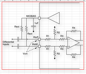
My customer is using PCM6240-Q1. As per datasheet, they are designing R0 resitor value based on ouput resitor of a mic.
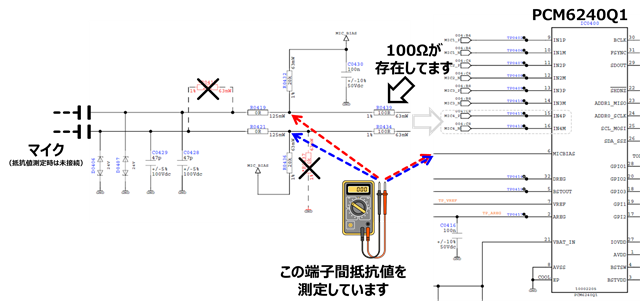
In their project, they may change the mic and thus may change R0 resistor value. To test that the resitor change is approprately done, they are going to measure resistor value between MICBIAS pin and INxP pin and MICBIAS pin and INxN pin.
When they measured resistance between MICBIAS pin and INxP/INxN pins, it was 40.4kohm without R0. When they populate 20kohm resistor, resistance between MICBIAS pin and INxP/INxN pins was 16.7kohm.
Thus, it seems this is not simple parallel resistor circuit.
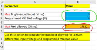
1. How can they calculate resistance between MICBIAS pin and INxP/INxN pins when they populate R0?
2. When they populate 20kohm resistor, the 16.7kohm measurement result correct?
Thanks,
Kento