Other Parts Discussed in Thread: CC3200AUDBOOST, CC3200
Tool/software:
Hi Sir:
I have CC3200AUDBOOST EVB which is TLV320AIC3254 on that EVB.
https://www.ti.com/tool/CC3200AUDBOOST
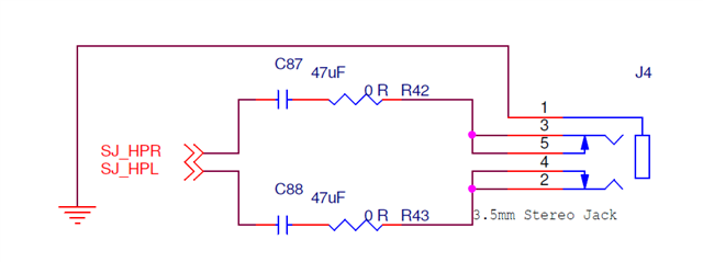
Currently. the music data can streaming from smartphone to BT module over I2S --> to TLV320AIC3254 --> HPR/HPL
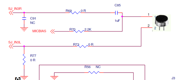
Based on EVK schematic. there is microphone on the EVB.
I just confused how to configure register make voice sound to I2S OUT???
Please hele to review the register setting. Thanks.
if(mic & AUDIO_CODEC_MIC_ONBOARD)
{
reg1 |= 0x40; // MICBIAS powered up
reg2 |= 0x00;
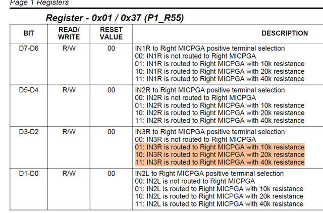
reg3 |= 0x04;
reg4 |= 0x04; // IN3R is routed to Right MICPGA with 10k resistance
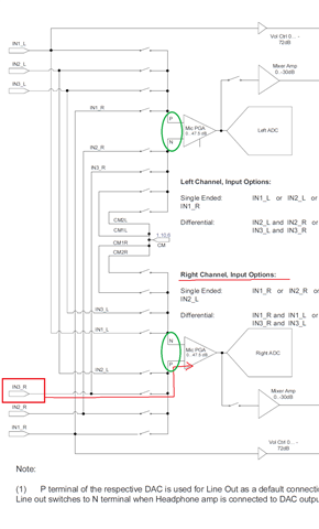
reg5 |= 0x40; // CM is routed to Right MICPGA via CM1R with 10k resistance
reg6 |= 0x04; // IN3R input is weakly driven to common mode. Use when not routing IN3R to Left and Right MICPGA
}
tlv320aic_page_select(TI3254_PAGE_1); //Select Page 1
tlv320aic_write_reg(TI3254_MICBIAS_CTRL_REG, reg1);
//Route IN2L not routed
tlv320aic_write_reg(TI3254_LEFT_MICPGA_P_CTRL_REG, reg2);
//Route IN2R CM1L to LEFT_N with 10K input impedance
tlv320aic_write_reg(TI3254_LEFT_MICPGA_N_CTRL_REG, reg3);
//Route IN2R to RIGHT_P with 10K input impedance
tlv320aic_write_reg(TI3254_RIGHT_MICPGA_P_CTRL_REG, reg4);
//Route CM1R to RIGHT_M with 10K input impedance
tlv320aic_write_reg(TI3254_RIGHT_MICPGA_N_CTRL_REG, reg5);
tlv320aic_write_reg(TI3254_FLOAT_IP_CTRL_REG, reg6);
//make channel gain 0dB, since 20K input
//impedance is used single ended
tlv320aic_write_reg(TI3254_LEFT_MICPGA_VOL_CTRL_REG, 0x00); // 0.0dB
//Unmute Right MICPGA, Gain selection of 6dB to
//make channel gain 0dB, since 20K input
//impedance is used single ended
tlv320aic_write_reg(TI3254_RIGHT_MICPGA_VOL_CTRL_REG, 0x00); // 0.0dB
tlv320aic_page_select(TI3254_PAGE_0); // Select Page 0
// Set I2S Mode and Word Length 16 bits
//tlv320aic_write_reg(TI3254_AUDIO_IF_3_REG, 0x10); //BCLK is output from the device, WCLK is input to the device
tlv320aic_write_reg(TI3254_LEFT_ADC_VOL_CTRL_REG, 0x68); // -12dB
tlv320aic_write_reg(TI3254_RIGHT_ADC_VOL_CTRL_REG, 0x68); // -12dB
//tlv320aic_page_select(TI3254_PAGE_0); // Select Page 0
//Power up LADC/RADC
tlv320aic_write_reg(TI3254_ADC_CHANNEL_SETUP_REG, 0xC0); // Left and Right Channel ADC is powered up
//Unmute LADC/RADC
tlv320aic_write_reg(TI3254_ADC_FINE_GAIN_ADJ_REG, 0x00); // Left and Right ADC Channel Un-muted. Left and Right ADC Channel Fine Gain = 0dB,
Austin