This thread has been locked.

If you have a related question, please click the "Ask a related question" button in the top right corner. The newly created question will be automatically linked to this question.

TAS6424-Q1: Diagnostics are not updated for DC Load properly once we remove the DC load

Part Number: TAS6424-Q1
Other Parts Discussed in Thread: TAS6424, TAS6424E-Q1, TAS6584-Q1

Tool/software:

Hello TI Support Team,

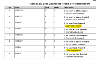
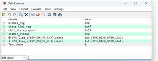
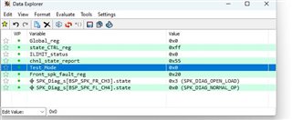
We are interested in reading the DC Load Diagnostic for Registers 0x0C and 0x0D. When we connect an external load, such as a speaker, to Channels 1, 2, 3, and 4 for both front and rear speakers, a Short to Battery, Ground, and Open DC Load are detected without issue.

Once we connect the DC load (external speakers), we expect the register values from 0x0C and 0x0D to be 0x00, as there is no fault across all channels. This is the observation we are currently seeing.

However, when we remove the external speakers, the fault should reset, resulting in a non-zero value, specifically with the 1st and 5th bits set. Unfortunately, the fault is not resetting as expected.

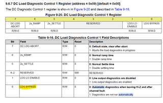
Could you please advise if there are any other configurations or registers we should consider adjusting in our Init() function to resolve this issue?

        TAS6424_WriteReg(TAS6424_REG_MODE_CTRL_ADDR, 0x80);
        TAS6424_WriteReg(TAS6424_REG_MODE_CTRL_ADDR, 0x00);
        TAS6424_WriteReg(TAS6424_REG_SAP_CTRL_ADDR, 0x46);
        TAS6424_WriteReg(TAS6424_REG_CH_STATE_ADDR, 0x00);
        TAS6424_WriteReg(TAS6424_REG_CH1_VOL_ADDR, 0xC9);
        TAS6424_WriteReg(TAS6424_REG_CH2_VOL_ADDR, 0xC9);
        TAS6424_WriteReg(TAS6424_REG_CH3_VOL_ADDR, 0xC9);
        TAS6424_WriteReg(TAS6424_REG_CH4_VOL_ADDR, 0xC9);
        TAS6424_WriteReg(TAS6424_REG_DC_DIAG_CTRL_ADDR, 0x02);
  • The DC Diagnostics only works when the device is in Hi-Z state.  It is not a real time load diagnostics.  If you removed the speaker load, you will need to place the device into Hi-Z mode and then run the load diagnostics.

    Regards,
    Gregg Scott

  • Hello Gergg Scott,

    Thank you for your reply. We will try this tomorrow. Meanwhile, I wanted to share one more observation:

    Once the load is connected to any of the channels, we notice that the Global Faults 1 Register value is 0x10, indicating a clock fault is detected.

    Is this normal in Play mode, or should we expect this in the Hi-Z state as well?

    Additionally, do we need to enable the AC Diagnostics to test the Speaker Load Diagnostic?

  • AC Load diagnostics and clock faults are two different mechanisms.  You need to solve the clock fault issue.  You need to make sure you have the proper clocks with exact integer multiples of Fsync.  If they are not exact you will get intermittent clock faults.  You can also see clock faults if the ground return from our device to the TDM source.

    Regards,
    Gregg Scott

  • Hello Gergg Scott,

    We tried testing the load diagnostic in Hi-Z mode by connecting speakers to the channels.

    However, we always read a value of zero (0x00) from registers 0x0C and 0x0D.

    Even when connecting a Short to GND or VCC in Hi-Z mode, the register values remain the same, i.e., 0x00.

  • Sunilkumar,

    You can look at this e2e thread for help:(11) TAS6424E-Q1: Diagnostic Function - Audio forum - Audio - TI E2E support forums

    This provides the timing necessary for DC load diagnostics to finish so that you can read the values back.

    Regards,
    Gregg Scott

  • Hello Gregg Scott,

    Thank you for your reply.

    We are reading the Diagnostic register every 10 ms, and we are also checking the modes every 10 ms; however, the status always remains in Play mode.

    When we change the state to Hi-Z mode, both Diagnostic register values are zero.

    We are facing an issue related to DC Load Diagnostic. Here are some observations:

    As explained earlier, this is what we observe in Play mode:

    • If we connect the respective channels to GND or VCC, we can detect a fault value (“Short-to-GND detected” or “Short-to-Power detected”) in the respective registers, 0x0C and 0x0D.
    • Once we disconnect the channels from GND or VCC, we can see the Open Load bit set (“No short-to-GND detected,” “No short-to-power detected”) as expected.
    • During this time, we do not observe any values in the Global Faults 1 Register.

    Load Test:

    • When we connect external speakers to the respective channels, the 0x0C and 0x0D register values indicate "No open load detected" as expected.
    • Once we remove the external load from the channel, we expect the "Open load detected" bit to be set, but this bit is never set.
    • During this time, we observe that the Global Faults 1 Register value is 0x10, indicating a clock fault is detected.

    Could you please provide guidance or suggestions on addressing this issue?


  • During the load test in the scenario above I interpret that you are testing open load in step 1 with the automatic DC load diagnostics when you take it out of STANDBY mode.  In step 2, I am interpreting that you are taking the load off and expecting a change without running the DC load diagnostics.  And, I have no idea why you see a Clock fault.  This is separate from the DC Load diagnostics.  

    In automatic load diagnostics when taking the device out of STANDBY, the channel with a faulty connection will be tested approximately every second, forever, until the load is corrected.  Automatic DC Diagnostics can also be terminated by an abort signal via I2C or placing the device in STANDBY mode.

    If you have everything working correctly after taking it out of STANDBY, and then take the load off, it will not be detected.  You need to run DC Diagnostics through I2C commands. 

    Regards,
    Gregg Scott

  • Hello Gregg Scott,

    Thank you so much for your reply.

    As you know, we are currently running in Play Mode. After testing GND and VCC, the mode remains unchanged, and we observe the same mode while testing (Fault) Load.

    I have a few questions:

    1. Do we need to monitor the STANDBY pin 24 during this process?
    2. Do we need to set the PHASE_SEL 5th bit in register 0x28?
    3. For Load Fault detection, do we need to enter a command in register 0x09 again, as shown in the below snapshot?

    Could you please provide guidance on these points?

  • When in play mode, the DC load diagnostics does not function.  

    In play mode:

    • A short to power will trigger a over current fault.  If automatic load diagnostics is enabled, it will run DC load diagnostics one after the and then wait for a user interaction.
    • A short to ground will trigger a over current fault.  If automatic load diagnostics is enabled, it will run DC load diagnostics one after the and then wait for a user interaction.
    • An open load will not trigger a fault or run load diagnostics.  Nothing will change
    • A shorted load, may trigger a CBC warning if the signal is large enough and the short is low enough in resistance.  This will not trigger a DC load diagnostics

    During play there is no way to have load diagnostics.  It is not designed into this device.

    Regards,
    Gregg Scott

  • Hello Gregg Scott,

    Could you please advise on what we need to do for the Speaker Load Diagnostics? We have performed tests in all four modes, but there is no update on the DC Diagnostics registers 0x0C and 0x0D.

    1. In Hi-Z mode, when we perform DC Speaker Diagnostics, registers 0x0C and 0x0D always show ZERO.

    2. In DC Diagnostics mode, register 0x0D always reads 0x03, even though nothing is connected.

    Could you please let us know if this device supports the Speaker Load Diagnostic feature?

  • Sunikumar,

    How long are you waiting before you read the DC Load Diagnostic registers?  500ms is the worst case when all 4 channels are open load.

    Regards,
    Gregg Scott

  • Hello Gregg Scott,

    We are continuously reading the Diagnostic register every 100 ms as part of a cyclic task. We connect the speakers 1 minute after starting our software, but we are unable to detect the Load Speaker on registers 0x0C and 0x0D.

    regards,

    Sunilkumar Chawhan

  • Sunikumar,

    In your attached graphic above, the output shows open load.  Do you have speakers connected?  In the comment #2 above, it says nothing is connected.  

    What is the difference in the test between #1 and #2 above.

    Regards,
    Gregg Scott

  • Hello Gregg Scott,

    As mentioned in my previous comment, we initially did not connect anything to Channel 3, which corresponds to Register 0x0D. The behavior remains the same as shown in the figure, and with STB and Speaker load, there is still no change in the register value.

    We are currently unsure of what else needs to be done to perform the Speaker load diagnostic. Could you please provide some guidance?

    1. When we change mode to DC Diagnostic mode on 0x04 register: 0xff

    no change in the Register Front_spk_fault_reg which represents channel 3 and 4 (0xD)

    2. When we change mode to Hi-Z mode on 0x04 register: 0x55

    no change in the Register Front_spk_fault_reg which represents channel 3 and 4 (0xD) : always zero

    3.When we change the mode to Play mode on register 0x04 by setting it to 0x00, there is no change in the Front_spk_fault_reg, which represents channels 3 and 4 (0x0D).

    Load Diagnostics will detect a fault and once we connect speaker the register value gets changed to No_OPEN_Load detected as expected, but it is latching, and the channel will not function(STB, STG, SL will not work) after it latches.

    Channel 4

    Channel 3

  • Sunikumar,

    In your step 1 above, the results are correct to the description.  Channel 3 is open load and channel 4 is correctly loaded.

    Does step 2 follow step 1?   I see that channel 3 is now showing a correct load.  Did you connect a speaker/load at this point?  

    In step 3, going from hi-z to play, DC load diagnostics will run unless it is bypassed in Register 0x09 bit 0.  It continues to run on an open channel and when a speaker is connected it will detect it.  Please read register 0x0F to see the state the channel it is in.  Which register is Front_spk_fault_reg?  If is register 0x10, there is an OC fault on channel 3 that needs to be cleared.  If so, this will block the channel.

    In the Channel 4 graphic:
    The channel state of 0xfc, does not properly reflect the spk diag state for channel 3 and 4. They are reversed.

    In the channel 3 graphic:
    All looks correct.

    Regards,
    Gregg Scott

  • In the graphic, the variable "chal_state_report" belongs to register "0x0F."

    Graphic 1: Before starting the software, if we connect the speaker load to the channels for the first time, the value updates in DC diagnostic mode. However, after starting the software and connecting the speakers to the channel, it won't detect anything at all.

    Graphic 2: If we manually set register 0x04 to Hi-Z mode, we receive values in the 0x0D register, which represents the variable "Front_spk_fault_reg."

    Graphics 3 and 4: We manually set the mode to Play in register 0x04, which corresponds to the graphic variable named "state_CTRL_reg." For the first time, if we connect the load, the Front_spk_fault_reg changes accordingly. However, if we then remove the speaker, the Front_spk_fault_reg register value does not change, as it is latching.

    If possible, could we have a meeting or Teams call? It would help us understand our issue more quickly.

  • Sunikumar,

    Automatic load diagnostics has some quirks that you need to understand.  When the device is taken out of STANDBY mode it automatically runs.  If all the channels are ok, it will stop running load diagnostics and set the report to 0x00.  If there is a fault on a channel, such as open load, that channel will continue to run load diagnostics every second and report an open load.  When you connect a speaker, it finds the load because it has been running the load diagnostics every second and it will report that the load is present.    This does not work the opposite way, if you have a good load, then remove the speaker, it will not indicate the load is missing as the automatic load diagnostics stopped on the previous good load.  

    Once you have a good load indication, you can transfer the properly loaded channels to play.  On these channels the load diagnostics is not running and if you remove a speaker, it will not be indicated.   And channels with an improper load as indicated in 0x0D register cannot move to Play mode.  It will be stuck in Load Diagnostics. 

    The latching effect you state is because the load diagnostics is not working on a channel when the speaker is removed after a good result. 

    Our DC load diagnostics cannot be used to detect a speaker when it is in play mode.

    Regards,
    Gregg Scott

  • Hello Gregg Scott,

    After having the discussion on this Monday, we have some queries:

    Without resetting the slave device using I2C (by writing 0x80 into the Mode Control Register (0x00)), we are unable to obtain the speaker load diagnostics.

    However, resetting the slave device interrupts the speaker playback, as it stops playing during the reset, which occurs every 5 seconds as we are updating the Play mode every 5 seconds periodically hence its interrupts the Playback of speaker.

    Please suggest a solution for obtaining speaker load diagnostics without interrupting the speaker playback

    Regards,

    Sunil Chawhan

  • Sunil,

    As we discussed during our phone call, the TAS6424E-Q1 does NOT have this feature.  For a short to ground or a short to power, we have over current protection.  For a shorted load, we can look at the CBC warning or over current protection (this is signal level dependent).  For open load, there is no way to detect this while in play.

    If you need real time load diagnostics, you can implement an external circuit that could detect the current in the speaker.  The current can be compared to the output voltage to determine whether the speaker is open load or shorted load.

    Or, you can use the TAS6584-Q1 device that has the Real Time Load Diagnostics built in.

    Regards,
    Gregg Scott