This thread has been locked.

If you have a related question, please click the "Ask a related question" button in the top right corner. The newly created question will be automatically linked to this question.

TAS5825M: Noise when spread spectrum activated

Part Number: TAS5825M

Tool/software:

Hi,

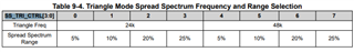
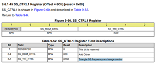
We have implemented some TAS5825M on a board and we have some amplifier that have an excess of output noise when the spread spectrum is activated. 

We change the value of the spread spectrum and the noise is reduced. When we disabled the spread spectrum the noise return to the normal condition.

Noise when spread spectrum  = 300µVrms

Noise without spread spectrum = 50µVrms

The ratio of increasing is not the same on each amplifier and the 6x ratio seems big, is it normal? Thanks in advance.

  • Hey Pierre, 

    Thanks for coming to e2e with your question. Please share a schematic for further evaluation. 

    Regards,
    Ore.

  • Hey Pierre, 

    I still encourage sending a schematic for review. Comparing the noise levels provided, it is important to understand the spread spectrum(SS) feature typically spreads frequencies occupying a narrow band across a wider band. This is for improving EMI performance. This increase in bandwidth of any frequency introduces noise to the IC's audio band, hence the higher noise value when SS is enabled.

    I would try decreasing the spectrum triangle frequency and spectrum range while watching the noise floor. Within the register map, find reg x6C. I have images below describing how to configure these parameters.

    -------------------------------------------------  

    register bits in x6C that configure SS.

    Register Map definition of regx6C.

    I hope this was informative, if more support is needed regarding this application or its schematic please share in this thread. Check out this other e2e that mentions trade-off for using spread spectrum. More noise in the spectrum is expected and configuring the specs could change the idle channel noise floor.

    Regards,

    Ore. 

  • Hi,

    Thanks for the response, you can find the schematic below. Is there something to do in the layout to avoid this problem?

  • Hey Pierre,

    Thanks for providing the schematic, allow till tomorrow for a response.

    Regards,
    Ore.  

  • Hey Pierre,

    The schematic looks good to me. To further investigate this significant difference in idle channel noise floor, please share more info on the I2C portion of your setup. 

    What process flows on the IC are being used at the moment? if you could provide the current register settings/dump in a .txt file that show features enabled within the IC, that would be helpful. Add comments if possible to make reading easier.

    It seems different process flows increase the noise floor. Asides SS, are there other features enabled? Provide a register dump the IC is currently operating with. Preferably the w xx xx xx format if possible, find example below. Add enough comments and make a list here of the features in the thread for quick debugging.

    ------------------------

    example of a read and write format that could easily be replicated on our end

    Regards,

    Ore. 

  • Hey Pierre,

    I have a test using PPC3 GUI with SS enabled. This is the noise floor value I observed. 

    Regards,

    Ore. 

  • Hey Pierre, 

    If there are no updates. I think we can conclude enabling different process flows on the IC would change the noise floor significantly and I have provided an image showing the noise floor when only SS in enabled. For further experiments on your end, you could observe the noise floor value while enabling and disabling different audio process flows on your IC.. 

    I would consider this thread closed. 

    Regards,

    Ore.