This thread has been locked.

If you have a related question, please click the "Ask a related question" button in the top right corner. The newly created question will be automatically linked to this question.

LM48511SQBD: LM48511SQBD

Part Number: LM48511SQBD
Other Parts Discussed in Thread: LM48511

Tool/software:

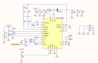
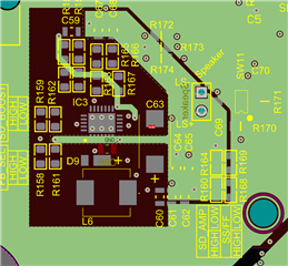
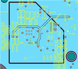
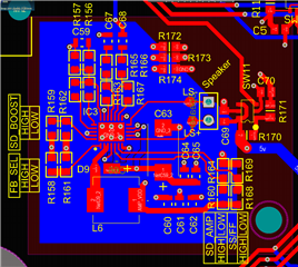
Hello, I have a personal PCB design with the LM48511, when activating the STEP-UP of the lm48511, SD_BOOST to VDD, the power supply drops and the IC heats up. It is tested without STEP-UP, SD_BOOST to GND and it works correctly but with low power.

Could someone help me figure out what the problem is? I'm attaching images of the schematic and layout.

  • Hi Leandro,

    Your schematic looks OK, pretty much following EVM directly, just have a couple questions:
    Is C63 a tantalum cap? You should use either ceramic or tantalum.
    What is the current rating of L6? I noticed this is higher inductance than the one used in the reference design.

    PCB layout does not raise a concern for me.

    A couple more questions about your debugging:
    Does the issue still happen even if the speaker is not connected?
    Have you tested on multiple devices?

    Best regards,
    -Ivan Salazar
    Applications Engineer

  • Hello Ivan, thanks for the quick response.

    Yes, the capacitor is indeed tantalum (T520V107M010ATE045). The inductor L6 is the one proposed in the datasheet (IHLP2525CZER6R8M01), with a current of 4.5A.
    The problem occurs whether the speaker is connected or not. One device burned out and two others heat up when SD_BOOST is enabled.

    Best regards,
    Leandro Sanchez.

  • Hi Leandro,

    Regarding the inductor, the schematic shows 8.2uH but you're actually using 6.8uH, is that correct?

    Have you verified the value of the components used for the boost feedback network?

    What is the voltage applied to AMP_VDD? Also what is the current capability of this power supply?

    Just looking for any possible reason at this point, it's not clear what could be the issue.

    Best regards,
    -Ivan Salazar
    Applications Engineer

  • Hello Ivan,

    The L6 is currently 8.2uH. I made a mistake when I said it was the IHLP2525CZER6R8M01, but in reality I placed the IHLP2525CZER8R2M1. So I have an 8.2uH inductor instead of 6.8uH.
    AMP_VDD comes from a 5V 2A regulator.
    Yes, the resistors and capacitors of the boost feedback network are the recommended ones, 20k at 1% and 0.18uF capacitors.

    Could the over-dimensioning of the inductance be causing this fault?

    Thank you for the assistance and patience.

    Best regards,
    Leandro Sanchez.

  • Hi Leandro,

    If possible, I'd check with the lower inductance, not sure if this could be the root cause though.

    When you test the device without boost, do you see any unwanted behavior? Perhaps some oscillations, or different gain than expected.
    Have you tried with spread spectrum enabled and disabled?

    Best regards,
    -Ivan Salazar
    Applications Engineer