This thread has been locked.

If you have a related question, please click the "Ask a related question" button in the top right corner. The newly created question will be automatically linked to this question.

TPA3223: PoP noise when muted

Part Number: TPA3223

Tool/software:

Dear Sir,

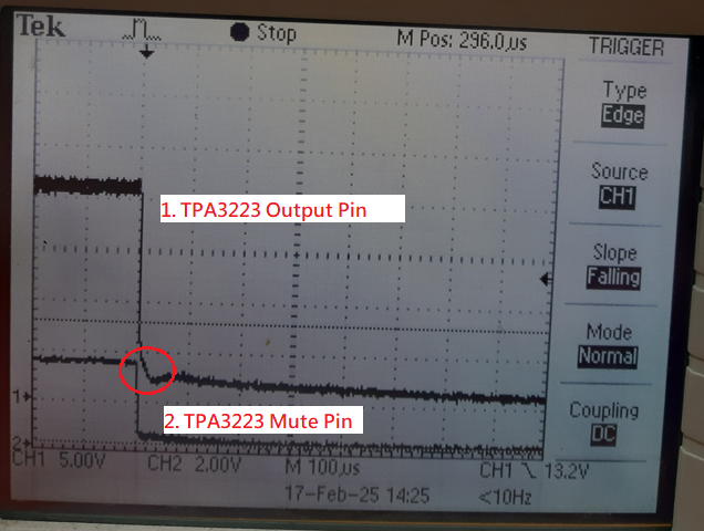
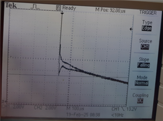
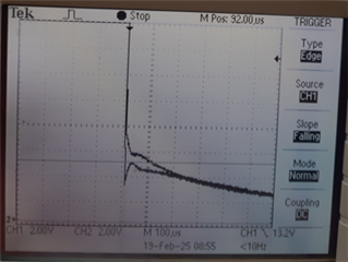
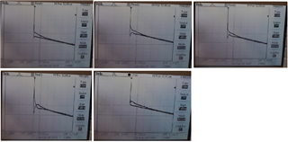
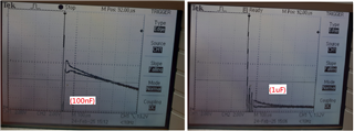
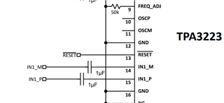
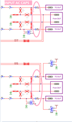
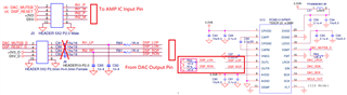
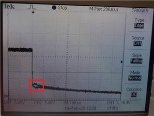
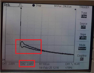
We heard the PoP noise when the TPA3223 went into Mute function and discovered the possible problem when measuring the TPA3223 output waveform. The problem seems to be caused by the voltage difference across the AMP IC, the waveform is as follows.


Our customers are waiting for a solution, please give us a suggestion to solve the problem or reduce the noise level.

Best Regards,

Tom

  • Dear Sir,

    Attached schematic diagram for analysis reference.

    TPA3223 schematic for Pop Noise Issue.pdf

    Best Regards,

    Tom

  • Dear Sir,

    The attached picture shows the relationship between the mute control sequence and AMP PoP noise for analysis reference.

    Best Regards,

    Tom

  • Hey Tom, 

    Expect a response tomorrow. 

    Regards,
    Ore.

  • Hey Ore,

    Looking forward to your reply.

    Best Regards,

    Tom

  • Hey Tom, 

    Here are my comments:

    • I see two filter configurations on the output channels. One ferrite bead to cap and one LC filter. I would recommend placing the ferrite bead filter before the LC filter as the cut-off frequency is higher on the ferrite filter than the LC.

    • Try impedance matching the input terminals for better voltage sensing. This is common practice for amplifiers. For example, if the differential impedance is 24kohms, connect 12kohms to GND on each input channel and very close to the input pins on a board layout. I have images below showing changing impedances per gain cfg.

    images

    ----------------------------------------------------------------------------------------

    Differential Input Impedance:

    Regards,

    Ore.

    Disclaimer: customer is responsible for customer's board design. TI is not responsible for design decisions on end applications.

  • Hey Ore,

    1. The test results are the same as before replacing the two EMI filters with 0R resistors, and there is still PoP noise. The waveform is as follows.

    2. After removing the input capacitor from the AMP IC input pin, the test results are the same as before, there is still PoP noise.  

    The waveform is as follows.


    Based on the test results, your suggestion does not solve the PoP noise problem.

    Best Regards,

    Tom

  • Hey Tom,

    I think you misunderstand my recommendations. 

    • The ac coupling caps are okay. After the caps, use impedance matching resistors like I have mentioned above. 
    • Leave the output filters in... instead of the ferrite bead to cap filter coming second, place the inductor to cap filter as the second filter and ferrite bead first. 
    • The 1nf to GND after the LC filter could be omitted too.

    Regards,

    Ore.

  • Hey Ore,

    1. The DAC analog output pin is directly connected to the AMP input via an AC coupling capacitor, without the impedance matching resistor you mentioned. I didn't find it in the TI EVM Board circuit diagram. Can you help point out where the impedance matching resistors are? Or can you help me draw the circuit?

    2. Do you suspect that the ferrite bead is causing the PoP Noise? If so, I have removed the ferrite bead but the result is the same and there is still PoP Noise. Removing 1nF also has the same result.

    Regards,

    Tom

  • Hey Ore,

    The attached picture is the TI EVM Board analog input circuit for your analysis reference.

    Regards,

    Tom

  • Hey Ore,

    The Impedance you mentioned seems to be that the AMP IC has different Gain settings corresponding to different input impedances and AC couplings and capacitance values, which will have corresponding low-frequency responses.

    Regards,

    Tom

  • Hey Tom, 

    Table 9-2 shows the lower limit of the 20KHz band needed for audio applications. Below is an example of how the external matching resistors should be routed. If differential resistance is 24K, then the external resistors should be 12K. This is not on the EVM, but it is common practice for amplifiers.

    Below is how the LC filter and ferrite bead filter should be configured. Place the ferrite bead filter before the inductor filter. You can take out C160 and C167 and I say this because pop noise usually occurs when the transient AC components (cap and inductor) are not closely matched. The cap to gnd from the ferrite bead and inductor are enough and adding an extra cap to gnd would mean more items to charge when a signal is passing through these terminals. For example, referring to the output terminal lines going to one speaker, one cap on one channel(OUT1_M) could charge faster than the other cap on the other channel(OUT1_P) and when this occurs pop noise could be significantly large. To reduce this, pick AC components with very small tolerances. For example, +-20% would be too high 

    Another option is increasing the capacitance on CMUTE, maybe 100nF instead. A slow ramp may improve the effect of pop.

    Some pop-noise is inevitable, but taking measures to match the paired input and output terminals to each other would make a huge impact on reducing pop noise. 

    I hope this is informative.

    Regards,

    Ore.  

  • Hey Ore,

    1. AMP input pin added impedance resistor using 12K ohms and PoP noise is the same as before. Modify the schematic as follows.


    2. Removed C160, C167 and FB2, FB4 and replaced them with 0 ohms, FB2, FB4 are for EMI purposes, PoP noise is the same as before. The picture is as follows.

    3. LC values ​​and tolerances: 10uH +/- 20% and  MLCC 1206 1uF/100V +/-10% X7R

    4. The noise volume of each PoP will not be the same. The waveforms measured multiple times are as shown below.

    Regards,

    Tom

  • Hey Ore

     Increasing the capacitance on CMUTE, used 100nF and 1uF instead and still have pop noise. he waveforms measured are as shown below.

    Regards,

    Tom

  • Hey Tom, 

    I have a couple questions:

    • I would like to ask if the pop-noise is audible or is this test validated over an oscope only?
    • And if the DAC IC before TPA3223 AMP is receiving a simultaneous mute function with the AMP in your debug?

    Regards,

    Ore.

  • Hey Ore,

    1. Small PoP noise can also be heard through the speakers at the same time.Our customers care about this issue.

    2. We use mute feature of AMP IC as Stand-By function to save power mechanism and the mute function of the DAC cannot improve this problem.

    Regards,

    Tom

  • Hey Tom,

    Thanks for the detailed feedback.

    Here are my comments:

    • Comparing the first pop-noise image in this thread using 2V/div as the scope scale with CMUTE using 33nF vs CMUTE using 100nF, the pop noise seems to ramp down faster and could suggests the noise is reducing.

    • I see no input AC caps? This is important for blocking DC noise from the input terminals that would show up at the output. Place these caps before the impedance matching ckt. So leading to the IC terminals would be the AC caps, impedance matching resistors and then the IC terminals. Use 1uF to 4.7uF like the DS and EVM respectively provide.

    DS:

    EVM:

    • I still recommend using lower tolerance inductors and caps to see a difference.

    Regards,
    Ore.

  • Hey Ore,

    1. Regarding the verification of the AC coupling capacitor, it was previously verified that the capacitor was removed but the PoP Noise was similar to before.

    2. Regarding the inductor using 10% tolerance parts, we ask the supplier to verify the difference in pop noise, if any.

    Regards,

    Tom

  • Understood. 

    Please do that. Lower tolerance for components that allow AC transients (caps and inductors) for both input and output channel configurations are encouraged to have any effect on pop-noise.

    Regards,

    Ore.