This thread has been locked.

If you have a related question, please click the "Ask a related question" button in the top right corner. The newly created question will be automatically linked to this question.

TAS5825M: Equalizer quick guide for non audio specialist

Part Number: TAS5825M

Tool/software:

Hi
We have made a system for a customer that has been in production for many years using the TAS5825M. We are very happy with the solution.
Now, the customer want us to make a equalizer and I hope we can get some help from PPC (purepath) to solve the problem.
We are not audio specialist but has general knowledge of filters, both analog and digital.

here is what i have done so far:
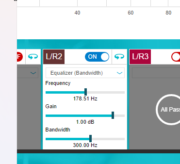
I run a test with one only L/R2 active. 

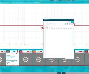
With this setting i generate a head file (#1)

Then, i change the gain to 0 and generate a new head file (#2) and compare the two files


What i can see is that 6 registers have a change in values when i change the gain from one to zero.

From this i have the following question.


How to calculate the values for this registers ?
Is there a quick guide or a document for dummies that can help us solve this task?
Our plan is only to change the gain in the equaliser and hopefully get the rest of the settings from the ppc3

Thanks

best regards
Mikal

  • hi Mikal

    how about this way:

    what you changed can get the script from the log tool.

    thanks

    jesse

  • Hi Mikal,

    The easiest way to calculate these values would be to use PPC3 as Jesse has shown, especially for a beginner. For a (semi) brief explanation, we can refer to this tuning guide and this app note. The app note goes into some detail about the register location of the DSP blocks for each process flow and the tuning guide has some information on the data format. The equalizer is made up of a bunch of individual biquads. In this case, L/R2 means that the biquads are "ganged" or apply to both the L and R channels. The biquad construction is made up of 5 coefficients that dictate the frequency response. The way these 5 coefficients are determined is based on the filter being used and there is no easy way of doing that calculation by hand. In the case of the filter you have used, with a gain of 1 vs 0, 4 of the 5 coefficients don't actually change. Since each register is made of 4 bytes of data, this corresponds to the 4 registers that are different. If you click on the arrow in the top right of the biquad you can see the actual coefficient values in decimal. PPC3 will do the conversion of these coefficients for you into the I2C like shown in Jesse's response, but if you need to do it yourself, the tuning guide describes the 5.27 data format and how it is stored so a script could be made to go from a decimal value to the register value.

    Regards,

    Ramsey

  • Thank you, I will forward to the software guy.

    I probably forgot to tell that we use a uC with a 7” LCD screen to control this. Om the screen we have 7 bars that we can drag up and down to add or remove Gain.

    So, we need to calculate this changes in the uC. I hope this input can help the SW team to make the calculation

    BR

    Mikal

  • FYI
    The sw team tell me that they have what they need to continue. I will return after a few days with an update
    Thanks :-)