This thread has been locked.

If you have a related question, please click the "Ask a related question" button in the top right corner. The newly created question will be automatically linked to this question.

PCM1780: Output wave form issue

Part Number: PCM1780

Tool/software:

Dear Expert,

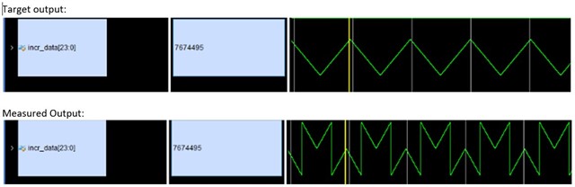
A customer is sending triangulated data from FPGA to PCM1780.  It's 24bit data per channel with the sequence  24'h7F_FFFF~24'h00_0000,24'hFF_FFFF~24'h80_0000~24'hFF_FFFF,24'h00_0000~24'h7F_FFFF.... that is 24bit complement data cycling from largest to smallest an repeat...

Customer is expecting a triangular wave form, but found the measured output is not.  It seems like the PCM1780 treated negative complement as positive number. (see picture description in below diagram).

Could you help to adv where may have gone wrong in the test?

Best Rgds,

Stanley

  • Hi Stanley , I have seen a similar problem with sinewave being sent from AP to different DACs and it seemed by shifting the data to left by one bit, the problem was gone. Basically the LSB of a frame was shifted into the next frame and thus it was the MSB bit for that frame.

    Please try to shift the data  ( not necessarily by one bit  )  and see if it fixes the problem. If not,  let me know and we will dig more by sending different data or pattern and monitor the signature of the output to figure it out.

    Regards,

    arash 

  • Arash,

    Customer feedback that the problem was due to setup timing issue.  If customer did the setting on PCM1780 first and output the CLK and data, it'll cause the problem.  But, if they wait for the FPGA to output the waveform for a while and reset the PCM1780, it will become normal.  Customer wants to know why.

    In addition, customer did another test by switching different audio signals (both 48KHz sample rate).   But, they will hear slightly chipped sound during switching.  Hence, customer would like to know why and how to avoid that.

    Best Rgds,

    Stanley

  • The customer feedback t is aligned with the what I mentioned above, that is  the input is shifted with respect the sync and BCK in one case. 

    If they want to understand what is changing in their different timing scenarios,  they have to screen capture the I2S for both cases to confirm the data is  shifted in one case compared to the other case. Based on my experience,  the input is shifted by one bit to right or left.

    It is also expected the hear some pop or noise  when  switching the signals or interrupting the  I2S while DAC is working. The work around is  to mute the DAC before switching the signal source or make sure you stay within the timing of internal reset with valid I2S.

    Regards,

    Arash