This thread has been locked.

If you have a related question, please click the "Ask a related question" button in the top right corner. The newly created question will be automatically linked to this question.

PCM3120-Q1: Read data is invalid with I2S at 96kHz and 32bit word length

Part Number: PCM3120-Q1

Tool/software:

Hello everybody,

I have a problem with the PCM3120-Q1, where I measue data with the I2S interface.

I apply a sine wave with 5 kHz on the input of the ADC.

When I configure the I2S interface with 96 kHz (real frequency is 100 kHz) and 32 bit word length, the measured signal looks like this:

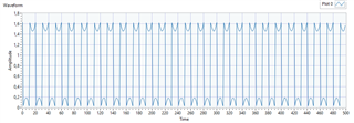
For me it looks like either there is a data conversion error or the signal is overshooting.

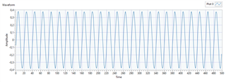
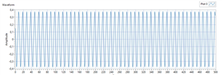
Anyway, when I configure the I2S interface at 100 kHz / 16 bit or 48 (real 50) kHz / 32 bit, the data looks correct.

So I assume, it's neither a data conversion error nor overshooting of the signal.

100 kHz / 16 bit

50 kHz / 32bit

My initialization of the PCM3120-Q1 looks like this:

// Set page to page 0x00
pcm3120_wr_reg(REG_PAGE_CFG, 0x00);

// Disable sleep
pcm3120_wr_reg(REG_SLEEP_CFG, 0x01);
// Sleep according to datasheet:
// "Wait for at least 1 ms to allow the device to complete the internal wake-up sequence"
HAL_Delay(5);

// Set ADC_FSCALE to 2d = "VREF is set to 1.375 V to support 1 VRMS for the differential input or 0.5 VRMS for the single-ended input"
pcm3120_wr_reg(REG_BIAS_CFG, 0x02);

// Set Channel 1 input type to "Line input"
pcm3120_wr_reg(REG_CH1_CFG0, 0x80);

// Set Channel 1 input impedance  to "Typical 10 kOhm input impedance"
pcm3120_wr_reg(REG_CH1_CFG0, 0x84);

// Set Channel 1 gain to 20 dB
pcm3120_wr_reg(REG_CH1_CFG1, 0x50);

// Enable input Channel 1
pcm3120_wr_reg(REG_IN_CH_EN, 0x80);

// Set ASI to I2S mode with 16 / 24 / 32 bit word length
pcm3120_wr_reg(REG_ASI_CFG0, 0x70); // 32 bit word length
// pcm3120_wr_reg(REG_ASI_CFG0, 0x60); // 24 bit word length
// pcm3120_wr_reg(REG_ASI_CFG0, 0x40); // 16 bit word length

// Enable ASI Channel 1 output
pcm3120_wr_reg(REG_ASI_OUT_CH_EN, 0x80);

// Power PLL and ADC channel
pcm3120_wr_reg(REG_PWR_CFG, 0x60);

I'm using a STM32 µC as host controller. My I2S configuration there looks like this:

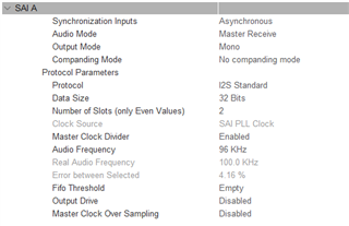
The only thing in the datasheet, where I found something related to this is the ASI_WLEN configuration, where it recommends to use 16bit word length with 10 kOhm input impedance (chapter 8.6.2.5 ASI_CFG0 -> ASI_WLEN):

ASI word or slot length.
0d = 16 bits (Recommended this setting to be used with 10-kΩ or
20-kΩ input impedance configuration)
1d = 20 bits
2d = 24 bits
3d = 32 bits


Can you help me fix this issue, or explain why 96 kHz / 32bit word length is not possible with this setup?

Thanks and best regards

Julian

  • Hi Julian,

    This is interesting, just to make sure you are using the device in target mode where the BCLK and WCLK are generated on your controller? So BCLK=32*2*100k = 6.4MHz? Do you have an MCLK being provided as well? 

    My thought is that there is maybe some PLL setting that the error between 96k and 100k is a little too high to correctly recognize, and there is some data truncation that messed up the two's complement signed data. I know normally clock differences of up to 5% are supported on some of our newer devices but this device does not have a spec'ed clock error difference where the device still works. Are you providing an MCLK that is a multiple of 48k? I think there is a chance we could set up the PLL manually and avoid this issue. Let me know your measured clock inputs.

    Can you read the ASI_STS register (0x15)?

    Best,
    Mir

  • Hi Mir,

    Thank you for your reply.

    Yes, the device is connected to my host controller and the controller is in I2S Master Mode and provides the BCLK and FSYNC signals. The MCLK is not connected.

    According to the datasheet, the f_bclk = f_fs * frame_length = 100k * 64 = 6.4 MHz (I also debugged this to be sure).


    Yes, I read the ASI_STS register. Originally, the default clock error of my controller was too high (can't remember, but was around 50%). As far as I remember, the ASI_STS read as 0xFF at that time. Then I tried to find a setting, where the ASI_STS didn't read "invalid sample rate", which resulted in the 100 kHz audio frequency.

    Now, the ASI_STS is 0x54 for the 100 kHz / 32 bit (and 0x52 for 100 kHz / 16 bit).


    I could try to find a host controller setting, where the audio frequency is much closer to the 96 kHz than it is at the moment. I just thought, when the ASI_STS replies a valid sample rate, that the device works correctly.

    Also I could connect an oscilloscope to take a look at the I2S bus and verify that the BCLK is correct.

    Best regards

    Julian

  • Hi Julian,

    I heard from a coworker that the maximum clock error for this device family is 3%. So, although it is detecting the closest supported sample rate of 96k, the device may not work correctly until the sample rate is around 98.88kHz... but yes, you should verify the I2S bus as well if you can to make sure the clocks are as expected with as little jitter as possible. Are you stuck with the 100kHz clock? Maybe you could switch to a different device, I believe our new line of converters such as TAA5x1x would support 100kHz sample rate with its more flexible PLL and clocking.

    Best,
    Mir

  • Hi Mir,

    I tried with some different clock settings on my controller and found a solution which has a I2S audio frequency of 95.833 kHz (Error -0.17%).

    Unfortunately it's the same behavior: 96 kHz / 16 bit and 48 kHz / 32 bit are working while the 96 kHz / 32 bit doesn't give me the correct data.

    I will ask a colleague from the hardware development for support with verifying the I2S bus and come back to you, if I have new information here.

    For the moment, we plan to continue with the PCM3120-Q1 device.

    Best regards,

    Julian

  • Hi Julian,

    Sounds good, yes please verify the I2S signals, and feel free to send scope shots here so I can take a look. It looks like there is some binary data issue since the amplitude of your 32 bit signal was 2x higher than the 16 bit signal at the same sample rate, as well as without the sign. 

    Best,
    Mir

  • Hi Mir,

    Thank you for your support so far. I come back to you, as soon as I have the scope shots.

    I made some new screenshots - with a smaller amplitude, but still sine 5 kHz. I think it's not a sign issue.

    96 kHz / 32 bit

    48 kHz / 32 bit

    96 kHz / 32 bit - more samples - sometimes have a single negativ peak

    Best regards,

    Julian

  • Hi Julian,

    Sounds good, send the scope shots when you have them. I can try to test this in the lab soon.

    -Mir