


Other Parts Discussed in Thread: TAS6424, TAS6424MS, TAS6424-Q1, TAS6424M-Q1, TAS6424L-Q1, TAS6424MS-Q1, , TAS6422E-Q1, TAS6424E
Tool/software:
Hello,
I wanted to use a TAS6424 evaluation board in PBTL.
I followed the diagram in the datasheet. I didn't succeed and the amp heated a lot.
With this diagram:
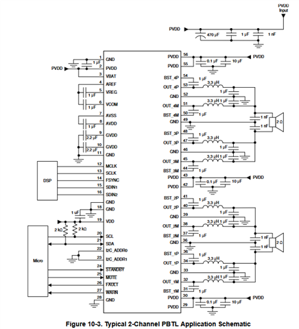
Looking at the evaluation board manual, the output wiring is different and appears consistent:
"TAS6424MS supports parallel Bridge-Tied Load. Channels 1 and 2 can be one PBTL channel and channels 3
and 4 can be the other. Before setting a set of channels to PBTL mode, connect the (+) terminals as PBTL
channel (+) and the (-) terminals as PBTL channel (-). Then connect the speaker (+) to the PBTL channel (+)
and connect the speaker (-) to the PBTL channel (-)."
This wiring works and allows you to obtain the powers announced in the datasheet in PBTL mode.
I think there is an error in the PBTL diagram (the outputs of each amp are short-circuited).
This concerns theses datasheets:
- TAS6424-Q1
- TAS6424M-Q1
- TAS6424L-Q1
- TAS6424MS-Q1
- TAS6424E-Q1
- TAS6422E-Q1
Please confirm the error.
Best regards
Loïc
