This thread has been locked.

If you have a related question, please click the "Ask a related question" button in the top right corner. The newly created question will be automatically linked to this question.

TAS5825M: High idle current and missing SDOUT

Part Number: TAS5825M
Other Parts Discussed in Thread: TAS5827

Tool/software:

I've got a board with 4 TAS585M chips. They pass audio as expected when configured with PurePath tool. But, as each chip is configured, the idle current goes up about 110mA per chip @24V PVDD. That's 2.64W for each chip. It is only this high if there is SCLK going to the chip. I see the same behavior on the TAS5825EVM board.

I think most of the power is being dissipated in the output filter inductors. They get fairly hot with no audio playing. I'm using the same inductors as the EVM BOM calls out, and see the same heating on my board as on the EVM. I did notice this idle current drops to about 80mA if I set the PWM clock from 384KHz to 768KHz.

Is this expected behavior? It seems much higher than the data sheet led me to believe, but I realize it is not spec'd at 24V.

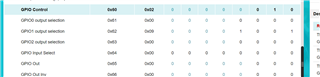
I'm also seeing another issue.  SDOUT does not output a signal. This is whether the origin is set to either PRE or POST EQ in PurePath. Is there some other configuration necessary to get a signal on DOUT?

  • hi, james 

    -can you tell me the load resistance you connected?

    -can you take a try with 1spw mode?

    -usually, the sdout should be outputted when the signal be played. if you have no signal be played, the sdout will have no output.

    thanks

    jesse

  • Hi Jesse,

    The speaker is 4 ohm, but the high current is the same with or without the load.

    Please clarify what you mean by 1spw mode?

    I am looking at SDOUT during signal playing and don't see any activity.

    James

  • Hi James,

    1SPW refers to the modulation type the device is using. It can be set in register 0x02 and is meant for low idle current applications. Can you read the GPIO registers (0x60-0x66) when the device is playing audio but no SDOUT is seen?

    Regards,

    Ramsey

  • I was able to set to 1SPW mode. That reduced idle current from about 125mA to 80mA. Then setting the FSW to 768K reduce idle current further, to ~70mA. This is with 24V PVDD. Is this about what is expected?  (This is eval board, but my board matches.)

    I can read the registers in PurePath while music is playing or not. 0x60 = 0x02, 0x61 = 0x00, 0x62 = 0x09, 0x63-0x66 = 0x00. These are with SDOUT origin set to Pre or Post in Simple Register Tuning window. Changing SDOUT origin to None causes 0x62 to go to 0x00. Does all this make sense?

  • hi James

    sorry for replying you late.

    24v with ~70mA seems reasonable. you can also check with low pvdd to see whether it is close to our DS.

    the sdout usually should be generally work default. connecting with PPC3, if the config is correct, when you playing signal, you should be able to observe the waveform at the sdout.

    thanks

    jesse

  • Hi Jesse,

    Thanks for the reply. I will check with lower PVDD, but it is good to know this is about what you expect with 24V. Regarding SDOUT, there is definitely no signal coming out with any of the settings in PurePath that I have mentioned. I've looked with a scope. Can you please send me a link to the most up to date document that describes all the register settings at the chip level?

    James

  • Hi Jesse,

    Ok some progress. I figured out that the register settings can change which GPIO pins are inputs or outputs, and configure what signals appear. The EVM board is different than my design.

    My design want SDOUT on GPIO2 pin 11. I've set up these registers which should accomplish that:

    0x60 = 0x04 (or in my case 0x05)

    0x63 = 0x09

    However, there is no SDOUT appearing on GPIO2. Any suggestions as to what might be wrong?
    James

  • hi James

    as i am not in office, cannot check with with evm.

    can you kindly check directly by adjusting by the GUI. you can change the corresponding bit to see how it config.

    have you set 0x62 to 00 which need to make current GPIO1 not work with sdout.

    thanks

    jesse

  • Hi Jesse,

    Yes, confirming I have set 0x62 to 0. My exact settings are:

    • 0x60 0x05
    • 0x61 0x0b
    • 0x62 0x00
    • 0x63 0x09
    • 0x64 0x02

    I think these are the correct settings to achieve this:

    • fault output on GPIO0
    • MUTEn input control on GPIO1
    • SDOUT on GPIO2

    If you could confirm this is correct that would be helpful. And just to confirm, I've saved these settings in a .ppc3 file, as well as a .cfg file (saving current settings). Reloading the .ppc3 file into PurePath shows the correct register settings. Loading the .cfg file into my board's amp, it isn't working. But I've yet to verify the .cfg file matches the .ppc3 as to register settings. Looking at the .cfg file, there are multiple writes to the same registers. Is there some way to confirm it matches the .ppc3?

  • Jesse,

    I now think I see what is going on. First off, setting the registers to the configuration I need, then saving the .ppc3 DOES NOT save the register settings in question. It seems that what gets save are a set of defaults, rather than the register values I have just set in PurePath in the window you showed. Consequently, when I dump to a .cfg file, it is not saving the settings I want, but rather the default settings. This explains why my board was not behaving as expected. However, if I manually add these settings to the .cfg file and load that into my board, IT DOES WORK as expected.

    Is there any way to fix this behavior?

    James

  • hi James

    ppc3 can only output the config file which be set in "tuning and process" block.

    as the tas5825 has no gpio config in the "tuning and process" block which lead to the output config can only generate default gpio config.

    if using different gpio setting, it needs manually change in the generated config file.

    let me discuss with ppc3 team to see whether they can help adding gpio config in the GUI.

    our next generation GUI like tas5827,5828, they can config gpio in the gui. this problem be solved.

    thanks

    jesse

  • Jessie,

    Ok, that explains what I'm seeing. It would be great if the PPC3 team could add an option to include the register settings in the .cfg file. That would make my application easier.

    In the meantime, is there a way to dump the register settings to a log file or window? I've looked for this and can't find it.

    James

  • hi James

    sure, i will confirm with our ppc3 team to update this.

    the log can be found as below: