This thread has been locked.

If you have a related question, please click the "Ask a related question" button in the top right corner. The newly created question will be automatically linked to this question.

TLV320AIC3110EVM-U: TLV320AIC3110EVM-U

Part Number: TLV320AIC3110EVM-U

Tool/software:

Hi Sir,

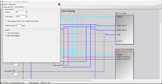
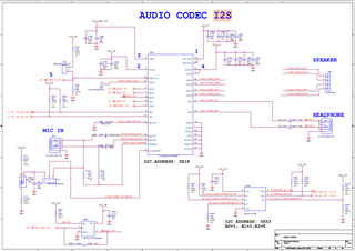
Actually I am trying to validate my I2S as a part of it I am tring to connect my cpu to audio codec and tring to play a sine wave and configure the codec in recording mode with I2C so that codec receives the audio samples and after I enable the I2S I can receive the samples on i2s side from codec but I am not getting any samples. I have followed a AIC3110_init configuration in codec folder for configuring in recording mode. So can you please help me in suggesting the working configuration in recording mode and how can I proceed doing this

Thanks and Regards,
Geetha. 

  • Hi Geetha,

    If you want to have the I2S data sent to the codec return back to the host PC, use the DIN to DOUT loopback in the EVM GUI. This option is found in the clock configurations.

    Best regards,
    Jeff McPherson

  • Hi Sir,


    Actually I am not connecting the GUI to my board, I am just using the script for ACI3110 init and Record init. I have used the script in codec. For recording mode I have connected CPU to my audio codec on fpga board and playing a sine wave. But I am not getting any sine wave samples on the i2s I have already configured the i2s in receive mode and verified the path on i2s side, from codec side I am not getting the correct sample. So, what script can I use and what are changes I can do in the script.


    Thanks and Regards,
    Geetha

  • Hi Geetha,

    Could you share a block diagram of your set up? It is not clear to me what paths you have working and what path is not working. You are sending I2S samples to the codec but there is no analog sine wave output?

    Also if you can include your current register configuration that will help me.

    Thank you,
    Jeff McPherson

  • Hi sir, 

    you can fine the block diagram below attached what we are using,


    And to send an audio data to the codec I am connecting jack pin from cpu to codec mic_in and play a sound like sine wave.
    And try to receive it on i2s (sdout pin).But can not see any data on the sdout.


    And below is the codec register configuration first to initialize the codec and then to initialize it in recording mode.

    #include<stdio.h>
    #include<stdlib.h>
    #include<stdint.h>
    #include "i2c_driver.h"
    #include "audio_codec.h"
    #define speedmode 0x63
    #define CODEC_ADDRESS 0x18

    void codec_initialize(void)
    {

    uint8_t write_address[]={REG_SELECT_PAGE,REG_SOFTWARE_RESET,REG_PLL_CLKIN_CODEC_CLKIN,REG_PLL_POWER_UP,REG_PLL_J,REG_PLL_D_HIGH,REG_PLL_D_LOW,REG_MODE_I2S_WORDLENGTH,REG_NDAC_POWER_UP,REG_MDAC_POWER_UP,REG_ADC_NADC_VAL,REG_ADC_MADC_VAL,REG_DOSR_HIGH,REG_DOSR_LOW,REG_DAC_VOLUME_CONTROL,REG_DAC_DRC_DISABLE,REG_DAC_GAIN_LEFT,REG_DAC_GAIN_RIGHT,REG_SELECT_PAGE,REG_DEPOP_POWER_ON,REG_HPL_HPR_POWER_UP,REG_DAC_ROUTE_TO_HPL_HPR,REG_HPL_UNMUTE_GAIN,REG_HPR_UNMUTE_GAIN,REG_ANALOG_VOLUME_HPL,REG_ANALOG_VOLUME_HPR,REG_MICBIAS,REG_ADC_P_TERM_INPUT_SEL,REG_ADC_M_TERM_INPUT_SEL,REG_SELECT_PAGE,REG_DAC_DSP_BLOCK,REG_SELECT_PAGE,REG_DAC_BUFFER_CONTROL,REG_SELECT_PAGE,REG_DAC_POWER_UP,REG_DAC_UNMUTE,REG_ADC_DIGITAL_MIC,REG_ADC_DIGITAL_VOL_FINE,0x00,0x23,0x23,0x26,0x27,0x23,0x23,0x26,0x27,0x2a,0x2b,REG_SELECT_PAGE,REG_CLASS_D_UNMUTE_LEFT,REG_CLASS_D_UNMUTE_RIGHT,REG_CLASS_D_POWER_UP,0x24,0x25};
    uint8_t write_data[]={0x00,0x01,0x07,0x91,0x20,0x00,0x00,0x00,0x84,0x84,0x84,0x84,0x00,0x80,0x00,0x00,0x00,0x00,0x01,0x4e,0xc2,0x44,0x0e,0x0e,0x00,0x00,0x0b,0x40,0x40,0x00,0x0b,0x08,0x04,0x00,0xd6,0x00,0x80,0x00,0x01,0x08,0x00,0x00,0x00,0x40,0x44,0x80,0x80,0x0d,0x0d,0x01,0x1c,0x1c,0xc6,0x30,0x30};

    int i;
    for(i=0;i<=(sizeof(write_address)/sizeof(write_address[0]));i++)
    {
    I2C_Start(CODEC_ADDRESS);
    slave_ack_i2c_address();
    I2C_Write(write_address+i, sizeof(uint8_t), write_data+i, sizeof(uint8_t));
    I2C_Stop();
    }
    }


    void codec_record_initialize(void)
    {
    uint8_t write_address_record[]={0x00,0x01,0x04,0x05,0x06,0x07,0x08,0x1b,0x0b,0x0c,0x12,0x13,0x0d,0x0e,0x00,0x2e,0x30,0x31,0x00,0x51,0x52};
    uint8_t write_data_record[]={0x00,0x01,0x03,0x91,0x08,0x00,0x00,0x00,0x84,0x84,0x84,0x84,0x00,0x80,0x01,0x0b,0x40,0x40,0x00,0x80,0x00};
    uint8_t read_buff[6];
    int i;
    for(i=0;i<=(sizeof(write_address_record)/sizeof(write_address_record[0]));i++)
    {
    I2C_Start(CODEC_ADDRESS);
    slave_ack_i2c_address();
    I2C_Write(write_address_record+i, sizeof(uint8_t), write_data_record+i, sizeof(uint8_t));
    I2C_Stop();
    }

    }


    Thanks and Regards,
    Geetha.

  • Hi Geetha,

    Thank you I understand the issue better now. While I study the code, can you tell me if the DOUT pin is showing any activity or toggling data? Or is it all low?

    Thank you,
    Jeff McPherson

  • No doout pin is low

    sometimes after loading the bitstream with out running the elf geting some garbage samples on dout pin.

    Thanks and regards,
    Geetha.

  • with out running the elf geting some garbage samples on dout pin.

    This seems like a typo. Can you clarify?

    Also you mentioned you based your script off the example initialization code. Do your I2S clocks match the frequencies given in the example?

    Thank you,
    Jeff McPherson