Other Parts Discussed in Thread: TLV320AIC3263,
Tool/software:
Hello,
I am using TI's TLV320AIC3263 codec series in my project, but I am experiencing some issues.
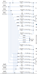
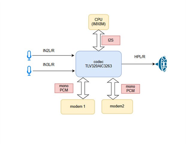
In my project, I need to use three audio interfaces:
- Audio Interface 1 (ASI1) is connected to the processor and uses the I2S protocol. The CPU is set as the master, and the codec is set as the slave. (MCLOCK= 48 Khz )
- Audio Interface 2 (ASI2) is connected to a modem1 and uses mono PCM. The Modem 1 is set as the master, and the codec is set as the slave. (BCLK = 2MHz WCLK=8KHz)
- Audio Interface 3 (ASI3) is connected to another modem2 and also uses mono PCM. The Modem 2 is set as the master, and the codec is set as the slave.(BCLK = 2MHz WCLK=8KHz)
The scenario is as shown in the attached diagram.
What I Want to Achieve
I want to route the audio signals received from IN2L/R and IN3L/R to any ASI interface dynamically. Additionally, I want to output the audio signals received from both PCM and I2S interfaces to the HPL/R (headphones).
Current Testing Setup
To begin, I attempted to test this setup using two ASI interfaces (ASI1 and ASI2).
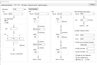
- I created a PWF file in PurePath Studio, as shown in the attached image.
- I can hear the mono PCM audio input through the headphones.
- The processor runs Linux, and when I use
aplay, I can hear the playback through ASI1. - I can record audio using
arecordon ASI1 in Linux.

Issue
However, I cannot hear the audio signals from IN2L/R and IN3L/R on ASI2.
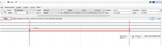
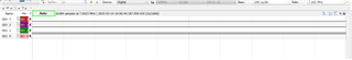
- When I send audio data through IN2L/R or IN3L/R, there is no change on the DataOut pin when monitored with a logic analyzer.
Question
Where could I be making a mistake? Can you help me troubleshoot this issue?
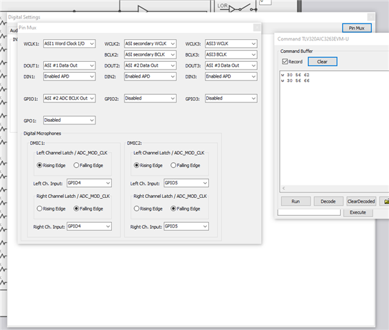
The registers I have configured are as follows:
w 30 7f 00 # Select Book 0
w 30 00 00 # Select Page 0
w 30 06 91 # R=1 J=24 D=0 P=1 PLL power up DIV=1
w 30 07 18 # R=1 J=24 D=0 P=1 PLL power up DIV=1
w 30 08 00 # R=1 J=24 D=0 P=1 PLL power up DIV=1
w 30 09 00 # R=1 J=24 D=0 P=1 PLL power up DIV=1
w 30 0a 01 # R=1 J=24 D=0 P=1 PLL power up DIV=1
w 30 05 10 # PLL source BCLK2
w 30 12 82 # ADC_CLK_pwr NADC = 2
w 30 13 98 # ADC_M_CLK_pwr MADC = 24 AOSR = 128
w 30 14 80 # AOSR = 128
w 30 0b 82 # NDAC = 2 power up
w 30 0c 84 # MDAC = 4 power up
w 30 0d 03 # DOSR 768
w 30 0e 00 # DOSR 768
w 30 04 33 # ADC and DAC source PLL_CLK
w 30 7f 00 # Select Book 0
w 30 00 04 # Select Page 4
w 30 12 01 # Data Offset
w 30 11 80 # Mono PCM 16 Bit Data word length
w 30 18 f0 # DAC output mono mix
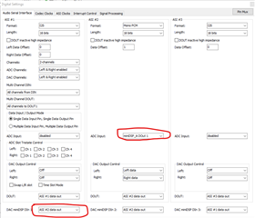
The register configurations related to routing are contained within the configuration (CFG) file generated by PurePath.
w 30 00 04 # Select Page 4
w 30 76 06 # DAC miniDSP IN1 ASI1 data out DAC miniDSP IN2 ASI2 data out DAC miniDSP IN13 ASI3 data out
w 30 08 50 # Data output control L/R
w 30 18 f0 # Data output mono mix
w 30 28 f0 # Data output mono mix
w 30 07 01 # ASI1 digital audio output data is sourced from ADC miniDSP Data Output 1
w 30 17 03 # ASI2 digital audio output data is sourced from ADC miniDSP Data Output 2
w 30 27 06 # ASI3 digital audio output data is sourced from ADC miniDSP Data Output 3