Tool/software:
Hello,
i'm trying without suces to get a toon out of de audio chip.
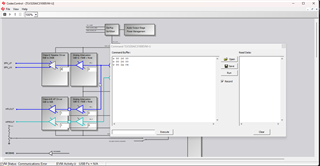
my setup is a mictrcontroler (stm32h743) connected toe de audio chip.
i can write and read the registers witch the i2c.
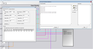
for start i wont to have a tone out of de autdio chipt witchout any external clock connected.
i'm not suceded in this task is hear notting and witch the scoop i have also notting.
have sombody a idea watts wronge wit te settings?
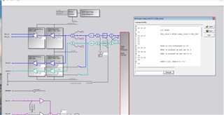
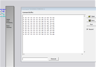
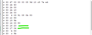
regiter settings that i uses:
# --------------------------------------------------------------- page 0 is selected
w 30 00 00
# s/w reset
> 01
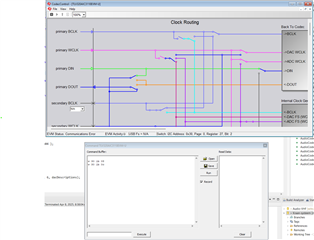
# PLL_clkin = BCLK,codec_clkin = PLL_CLK
w 30 04 07
> 91
> 20
> 00
> 00
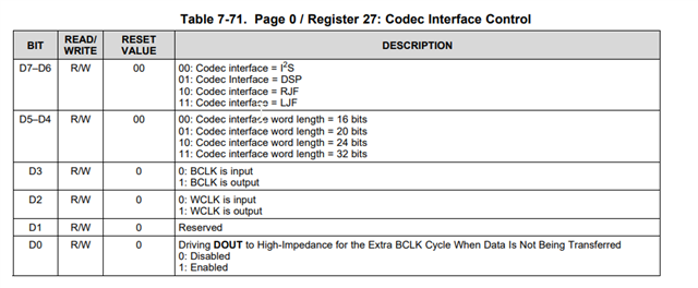
# mode is i2s,wordlength is 16
w 30 1b 00
# NDAC is powered up and set to 4
w 30 0b 84
# MDAC is powered up and set to 4
> 84
w 30 12 84
> 84
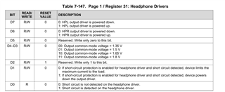
# DOSR = 128, DOSR(9:8) = 0
> 00
# DOSR(7:0) = 128
> 80
# DAC => volume control thru pin disable
w 30 74 00
# DAC => drc disable, th and hy
w 30 44 00
# DAC => 0 db gain left
w 30 41 00
# DAC => 0 db gain right
> 00
# --------------------------------------------------------------- page 1 is selected
w 30 00 01
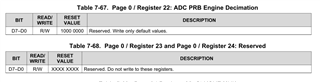
# De-pop, Power on = 800 ms, Step time = 4 ms
w 30 21 4e
# HPL and HPR powered up
w 30 1f c2
# LDAC routed to HPL, RDAC routed to HPR
w 30 23 44
# HPL unmute and gain 1db
w 30 28 0e
# HPR unmute and gain 1db
> 0e
# No attenuation on HP
w 30 24 00
w 30 25 00
# MIC BIAS = AVDD
w 30 2e 0b
# MICPGA P = MIC 10k
w 30 30 40
# MICPGA M - CM 10k
> 40
# --------------------------------------------------------------- page 0 is selected
w 30 00 00
# select DAC DSP mode 11 & enable adaptive filter
w 30 3c 0b
w 30 00 08
w 30 01 04
w 30 00 00
# POWERUP DAC left and right channels (soft step disable)
w 30 3f d6
# UNMUTE DAC left and right channels
> 00
# POWERUP ADC channel
w 30 51 80
# UNMUTE ADC channel
> 00
# --------------------------------------------------------------- page 1 is selected
w 30 00 01
# Unmute Class-D Left
w 30 2a 1c
# Unmute Class-D Right
w 30 2b 1c
# Power-up Class-D drivers
w 30 20 c6
best regards
Matthias