Tool/software:
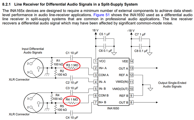
We're working on a pro audio device with differential inputs and chose the INA1650 as our line receivers. I followed the example circuit on page 22 of the datasheet called "8.2.1 Line Receiver for Differential Audio Signals in a Split-Supply System"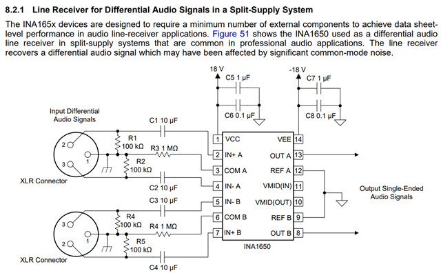
Now that the boards have come in I've been getting a lot of remarks on the design that I myself don't have any answers to:
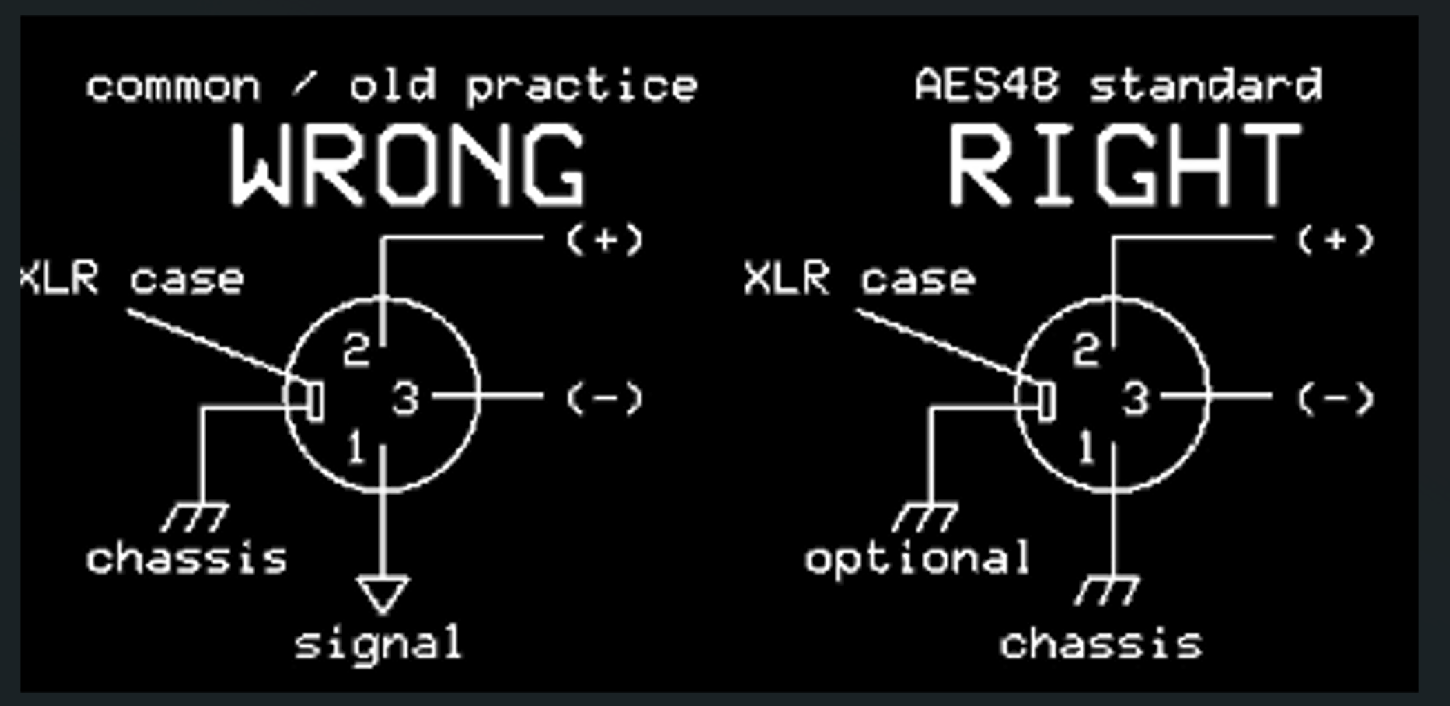
- Shouldn't the 100kΩ resistors have been connected to the system ground, instead of the chassis?
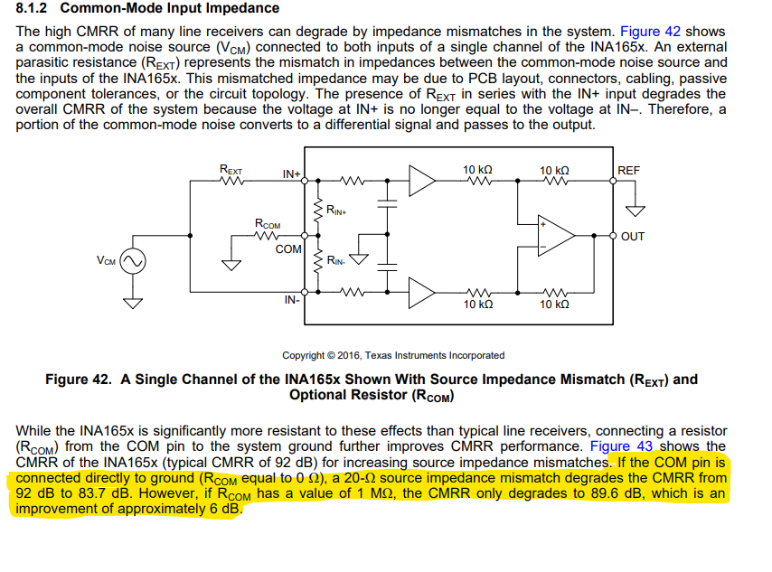
- Wouldn't a lower input impedance (instead of the 100kΩ per leg) be better, noise wise, and regarding static pops etc. when plugging in cables?
- Shouldn't R3 and R4 be connected to the system ground, instead of the chassis? I believe this is the case for the evaluation board, though it doesn't have a separate chassis.
I'm trying to run some tests to see what is 'best', but am struggling to find concise answers to these. I hope someone with more experience would be able to help me out!
Much appreciated,
David