This thread has been locked.

If you have a related question, please click the "Ask a related question" button in the top right corner. The newly created question will be automatically linked to this question.

TLV320AIC3204: Performance Issues: Channel Discrepancy and Noise Floor Concerns

Part Number: TLV320AIC3204

Tool/software:

Dear Texas Instruments Technical Support Team,

I'm writing regarding performance issues we've observed with the TLV320AIC3204 audio codec during our recent qualification testing for a new product design.

Our testing has revealed three specific concerns that we'd appreciate your insights on:

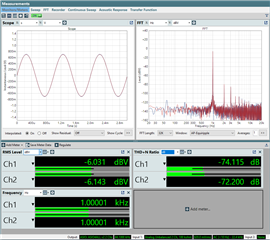
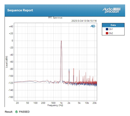
  1. ADC Noise Floor Performance: We're measuring higher than expected noise floor values in the ADC path. Our measurements show approximately -87 dBFS noise levels , which is significantly higher than what we expected based on the datasheet specifications.

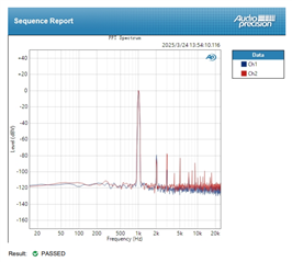
  2. DAC Output Gain Variation: We've observed unusually high output gain in the DAC path. The measured output levels exceed our expected values based on our configuration settings.

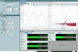
  3. Channel-to-Channel THD+N Discrepancy: Perhaps most concerning is the significant difference in THD+N performance between left and right channels. Our measurements show:

    • Left Channel (Ch1): 0.048664% THD+N
    • Right Channel (Ch2): 0.021597% THD+N

This represents more than a 2:1 ratio difference between channels, which exceeds our product specifications for channel matching.

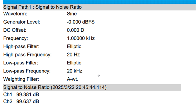
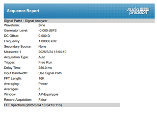
We've attached comprehensive test reports performed using ABTEC audio analysis equipment. All measurements were taken under controlled conditions with the following setup:

  • 48kHz sample rate
  • 24-bit resolution
  • Standard test signals at 1kHz
  • Input/output via professional audio interfaces with verified performance

Could you please advise if these observations are within normal operating parameters for the TLV320AIC3204? If not, we'd appreciate your recommendations for addressing these issues, whether through register configuration adjustments or potential hardware modifications to our implementation.

We're currently in the final stages of product development, so your prompt assistance would be greatly appreciated.

Thank you for your support.

Best regards,

Allen Su

  • Hi Allen,

    Can you please attach the test report as described by your mail?

    Also please include any register dumps/ set up scripts used for each of these tests.

    Thanks,
    Jeff McPherson

  • Hi Jeff,

    I've attached the requested ABTEC test reports for your review. 

    Also attached is our initialization code with the register configuration used during testing.

    HYPERX_XMOS-PHONES-TEST=1V.pdfHYPERX_XMOS-MIC-NOISE-TEST.pdftlv320aic3204.h

    CODEC_REGWRITE(AIC3204_PAGE_CTRL, 0x00);
    
        // Initiate SW reset (PLL is powered off as part of reset)
        CODEC_REGWRITE(AIC3204_SW_RST, 0x01);
    
        // Program clock settings
    
        // Default is CODEC_CLKIN is from MCLK pin. Don't need to change this.
        // Power up NDAC and set to 1
        CODEC_REGWRITE(AIC3204_NDAC, 0x81);
    
        // Power up MDAC and set to 4
        CODEC_REGWRITE(AIC3204_MDAC, 0x84);
    
        // Power up NADC and set to 1
        CODEC_REGWRITE(AIC3204_NADC, 0x81);
    
        // Power up MADC and set to 4
         CODEC_REGWRITE(AIC3204_MADC, 0x84);
    
        // Program DOSR = 128
        CODEC_REGWRITE(AIC3204_DOSR, 0x80);
    
        // Program AOSR = 128
        CODEC_REGWRITE(AIC3204_AOSR, 0x80);
    
        // Set Audio Interface Config: I2S, 24 bits, slave mode, DOUT always driving.
        //   CODEC_REGWRITE(AIC3204_CODEC_IF, 0x20);
        CODEC_REGWRITE(AIC3204_CODEC_IF, 0x30);     // 32 bit mode
        // Program the DAC processing block to be used - PRB_P1
        CODEC_REGWRITE(AIC3204_DAC_SIG_PROC, 0x01);
        // Program the ADC processing block to be used - PRB_R1
        CODEC_REGWRITE(AIC3204_ADC_SIG_PROC, 0x01);
        // Select Page 1
        CODEC_REGWRITE(AIC3204_PAGE_CTRL, 0x01);
        // Enable the internal AVDD_LDO:
        CODEC_REGWRITE(AIC3204_LDO_CTRL, 0x09);
        //
        // Program Analog Blocks
        // ---------------------
        //
        // Disable Internal Crude AVdd in presence of external AVdd supply or before powering up internal AVdd LDO
        CODEC_REGWRITE(AIC3204_PWR_CFG, 0x08);
        // Enable Master Analog Power Control
        CODEC_REGWRITE(AIC3204_LDO_CTRL, 0x01);
        // Set Common Mode voltages: Full Chip CM to 0.9V and Output Common Mode for Headphone to 1.65V and HP powered from LDOin @ 3.3V.
        CODEC_REGWRITE(AIC3204_CM_CTRL, 0x33);
        // Set PowerTune Modes
        // Set the Left & Right DAC PowerTune mode to PTM_P3/4. Use Class-AB driver.
        CODEC_REGWRITE(AIC3204_PLAY_CFG1, 0x00);
        CODEC_REGWRITE(AIC3204_PLAY_CFG2, 0x00);
        // Set ADC PowerTune mode PTM_R4.
        CODEC_REGWRITE(AIC3204_ADC_PTM, 0x00);
        // Set MicPGA startup delay to 3.1ms
        CODEC_REGWRITE(AIC3204_AN_IN_CHRG, 0x31);
        // Set the REF charging time to 40ms
        CODEC_REGWRITE(AIC3204_REF_STARTUP, 0x01);
        // HP soft stepping settings for optimal pop performance at power up
        // Rpop used is 6k with N = 6 and soft step = 20usec. This should work with 47uF coupling
        // capacitor. Can try N=5,6 or 7 time constants as well. Trade-off delay vs �pop� sound.
        CODEC_REGWRITE(AIC3204_HP_START, 0x25);
        // Route Left DAC to HPL
        CODEC_REGWRITE(AIC3204_HPL_ROUTE, 0x08);
        // Route Right DAC to HPR
        CODEC_REGWRITE(AIC3204_HPR_ROUTE, 0x08);
        CODEC_REGWRITE(0x0e, 0x08);
        CODEC_REGWRITE(0x0f, 0x08);
        CODEC_REGWRITE(0x12, 0x3a);
        CODEC_REGWRITE(0x13, 0x3a); //Gain-0DB
            // We are using Line input with low gain for PGA so can use 40k input R but lets stick to 20k for now.
        // Route IN2_L to LEFT_P with 20K input impedance
        CODEC_REGWRITE(AIC3204_LPGA_P_ROUTE, 0x20);
        // Route IN2_R to LEFT_M with 20K input impedance
        CODEC_REGWRITE(AIC3204_LPGA_N_ROUTE, 0x20);
        // Route IN1_R to RIGHT_P with 20K input impedance
        CODEC_REGWRITE(AIC3204_RPGA_P_ROUTE, 0x80);
        // Route IN1_L to RIGHT_M with 20K input impedance
        CODEC_REGWRITE(AIC3204_RPGA_N_ROUTE, 0x20);
        // Unmute HPL and set gain to 0dB
        CODEC_REGWRITE(AIC3204_HPL_GAIN, 0x06);
        // Unmute HPR and set gain to 0dB
        CODEC_REGWRITE(AIC3204_HPR_GAIN, 0x06);
        // Unmute Left MICPGA, Set Gain to 0dB.
        CODEC_REGWRITE(AIC3204_LPGA_VOL, 0x00);
        // Unmute Right MICPGA, Set Gain to 0dB.
        CODEC_REGWRITE(AIC3204_RPGA_VOL, 0x00);
        // Power up HPL and HPR drivers
        CODEC_REGWRITE(AIC3204_OP_PWR_CTRL, 0x30);
    
    
        CODEC_REGWRITE( AIC3204_PAGE_CTRL, 1); //page1
        CODEC_REGWRITE( 0x47, 0x32); //analog input quick charging configure
        CODEC_REGWRITE( 0x7b, 0x01); //power up config
        CODEC_REGWRITE( 0x33, 0x60); //---------0x78 used fail-------jian added ----MICBIAS
        CODEC_REGWRITE( 0x37, 0x80);
        CODEC_REGWRITE( 0x39, 0x10); // IN1L to RIGHT MICPGA with 10k ohm
        CODEC_REGWRITE( 0x3c, 0x2b); // 0x23 ==> 20dB Right MICPGA VOL --5a-45DB  5e--47db  :3d--ap实际测试25DB增益---跟客户样品一致 (一般30DB
        CODEC_REGWRITE( AIC3204_PAGE_CTRL, 0); // page0
        CODEC_REGWRITE( 0x54, 0x00); // _jian R_ADC volume 20DB
        CODEC_REGWRITE( 0x51, 0xc0);//
        CODEC_REGWRITE( 0x52, 0x00);//
    
        // Wait for 2.5 sec for soft stepping to take effect
        delay_milliseconds(2500);
    
    
        //
        // Power Up DAC/ADC
        // ----------------
        //
        // Select Page 0
        CODEC_REGWRITE(AIC3204_PAGE_CTRL, 0x00);
        // Power up the Left and Right DAC Channels. Route Left data to Left DAC and Right data to Right DAC.
        // DAC Vol control soft step 1 step per DAC word clock.
        CODEC_REGWRITE(AIC3204_DAC_CH_SET1, 0xd4);
        // Power up Left and Right ADC Channels, ADC vol ctrl soft step 1 step per ADC word clock.
        CODEC_REGWRITE(AIC3204_ADC_CH_SET, 0xc0);
        // Unmute Left and Right DAC digital volume control
        CODEC_REGWRITE(AIC3204_DAC_CH_SET2, 0x00);
        // Unmute Left and Right ADC Digital Volume Control.
        CODEC_REGWRITE(AIC3204_ADC_FGA_MUTE, 0x00);

  • Hi Allen,

    I can't find your -87dBFS result for SNR. Your SNR test in the report is showing 99dB which is higher than the typical amount (93dB)

    Your gain is higher by exactly a factor of 2. How are connecting the line outputs to the AP? Is it possible you are accidentally taking a differential measurement?

    I would use dB for the THD+N measurement, not %, so that it matches the datasheet better. I think the issue is related to the measurement method like above.

    Best regards,
    Jeff McPherson


  • MIC Noise.pdf0741.MIC.pdfSPK 512_driver.pdf This is AP test data. 
    test MIC: ADC in-i2s-USB Out(USB interface, XU316)
    test SPK: USB in(USB interface, XU316)-I2S-DAC out

  • Hi Jeff,

    Do you have any benchmark test reports for the TLV320AIC3204 EVK showing ADC low-noise performance and DAC-HP OUT specifications? These would be helpful for comparison.

  • Hi Allen,

    I don't have benchmark data on hand unfortunately. If needed I can compare on the bench.

    The SNR measurement should be valid. Here is the description of the SNR test

    I am not sure about the noise level test. Can you clarify my question above about how you have connected the AP to the EVM?

    Thank you,
    Jeff McPherson

  • Hi Jeff,

    Thank you for your response. Regarding the test results, I'm particularly concerned about the THD+N measurements between channels:

    • Ch1 0.021898 %
    • Ch2 0.048702 %

    This nearly 2:1 ratio difference between channels doesn't seem normal for a stereo codec. Such a significant channel mismatch would be problematic for our application.

    Could you please conduct comparative measurements on your benchmark platform to verify if this channel imbalance is expected behavior or indicates an issue with our implementation?

    Thank you,

  • Hi Allen,

    There is a bigger problem here. a factor of 2 would correspond to about 6dB difference which is a lot but it's not unusual for the two to be different within 3dB or so. However 0.02 percent is -37dB which is way worse than the datasheet spec. I would recommend redoing the test but observing the monitor and capturing the FFT. Or you can do the same in bench mode on the AP. Seeing the FFT will give a better hint as to why the THD+N is so bad.

    In parallel I will capture the output using comparable settings.

    Best regards,
    Jeff McPherson 

  • Hi Jeff,

    We've already conducted tests using two different instrument models and obtained similar results each time.

    We look forward to receiving your comparative test results.

  • Hi Allen,

    Is there an FFT of the result you can share?

  •   Please check the SPK 512_driver.pdf  report

  • Hi Allen,

    Thank you. I tested out this basic configuration script. And got the following results.

    # Software Reset
    ###############################################
    #
    # Select Page 0
    w 30 00 00
    #
    # Initialize the device through software reset
    w 30 01 01
    #
    ###############################################


    ###############################################
    # Clock Settings
    # ---------------------------------------------
    # The codec receives: MCLK = 11.2896 MHz,
    # BLCK = 2.8224 MHz, WCLK = 44.1 kHz
    ###############################################
    #
    # Select Page 0
    w 30 00 00
    #
    # NDAC = 1, MDAC = 2
    w 30 0b 81 82
    #
    ###############################################


    ###############################################
    # Signal Processing Settings
    ###############################################
    #
    # Select Page 0
    w 30 00 00
    #
    # Set the DAC Mode to PRB_P8
    w 30 3c 08
    #
    ###############################################


    ###############################################
    # Initialize Codec
    ###############################################
    #
    # Select Page 1
    w 30 00 01
    #
    # Disable weak AVDD in presence of external
    # AVDD supply
    w 30 01 08
    #
    # Enable Master Analog Power Control
    w 30 02 00
    #
    # Set the input powerup time to 3.1ms (for ADC)
    # w 30 47 32
    #
    # Set the REF charging time to 40ms
    w 30 7b 01
    #
    ###############################################


    ###############################################
    # Playback Setup
    ###############################################
    #
    # Select Page 1
    w 30 00 01
    #
    # De-pop
    w 30 14 25
    #
    # Route LDAC/RDAC to HPL/HPR
    w 30 0c 08 08
    #
    # Route LDAC/RDAC to LOL/LOR
    w 30 0e 08 08
    #
    # Power up HPL/HPR and LOL/LOR drivers
    w 30 09 3C
    #
    # Unmute HPL/HPR driver, 0dB Gain
    w 30 10 00 00
    #
    # Unmute LOL/LOR driver, 0dB Gain
    w 30 12 00 00
    #
    # Select Page 0
    w 30 00 00
    #
    # DAC => 0dB
    w 30 41 00 00
    #
    # Power up LDAC/RDAC
    w 30 3f d6
    #
    # Unmute LDAC/RDAC
    w 30 40 00
    #
    ###############################################

    I did see similar phenomenon as your report so some of this is just variance in the device. The attached picture shows the values in dBV and percent THD+N. It's not quite a factor of 2, but corresponds to about 1.2-1.5

    When you measure THD+N in percent, factors of two can seem large, but remember that a factor of 2 is only 3dB, and the THD+N is already quite low. If I change the measurement to dB, both values are in spec, but I understand the concern of the matching. This is just a trait of the device and not much can be done besides careful symmetrical layout design.

    I do have a concern that your THD+N is higher because your output is near 0dBV according to the FFT. The device can't support this output. The nominal is -6dBV. If I try to add 6dB gain the signal clips greatly. I would recommend reducing the output by 3-6dB and seeing if the THD+N improves.

    Best regards,
    Jeff McPherson