This thread has been locked.

If you have a related question, please click the "Ask a related question" button in the top right corner. The newly created question will be automatically linked to this question.

TAD5212EVM-K: How to get 1Vrms with stereo single-ended

Part Number: TAD5212EVM-K
Other Parts Discussed in Thread: TAD5212

Tool/software:

Hi,

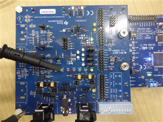
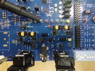
I'm evaluating TAD5212 using TAD5212EVM-K.

I'm considering using TAD5212 for 4-channel single-ended output.

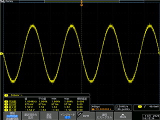
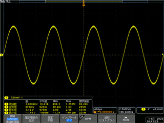
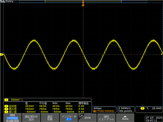
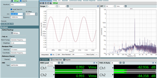
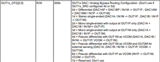
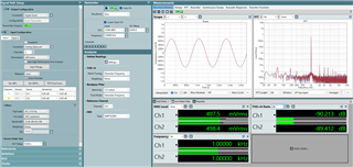
On PPC3, when "Stereo Single-Ended" is selected in the Output Config tab for OUT1x in the Playback Config section,  the output volume is only 500mVrms with the following settings although it is supposed to be 1Vrms according to the datasheet. With the same settings, when "Mono Single-Ended" is selected, the output volume is 1Vrms as intended.

  • Source: DAC Input
  • VCOM: 0.6*Vref
  • BW: Audio BW
  • Drive: Headphone
  • Level: 0dB

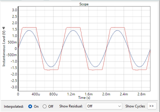
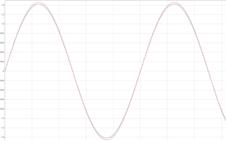
Also, the waveform of the output of Stereo Single-Ended is less smooth than that of Mono Single-Ended, looks like the resolution is reduced. USB audio is sent with 32bit length, 48kHz fs which are the same values as set in PPC3. 

I'd like to know how to get 1Vrms with Stereo Single-Ended.

Regards,

Ayako

  • Hi Ayako,

    I believe this output difference is because in mono single ended mode, the output is the combined output of DAC1A and DAC1B, vs for stereo single ended, the output is just one of those DAC outputs on each pin. To increase the output voltage, you can set the output level of the desired channel to 6dB, this will double the volume and should double the voltage as well, although you will not be able to go above 1Vrms output drive. I am surprised that the waveform is less smooth, can you post a scope shot here? 32 bit is plenty of resolution in the audio domain, you should not be able to hear a difference but maybe we can see one.

    Best,
    Mir

  • Hi Mir,

    Thank you for the reply.

    Now I understand the reason of the output difference between mono single-ended and stereo single-ended.


    I've attached a snapshot of the waveform of the output of OUT1P (CH1) when stereo single-ended is selected, with the output level set to 6dB. For comparison, I've also attached a snapshot of mono single-ended. *1kHz sine wave input at 0dB

    stereo  

    I'm also wondering why the level options of OUT1M (CH2) are only -8, -14, -20, and -26dB (shown in the snapshot below). How can I set the level of CH1 and CH2 to the same value?

    Best regards,

    Ayako

  • Hi Ayako,

    I tested this out in the lab, and I apologize but I think I was wrong about the output drive increasing at 6dB up. It seems that one pin of output (OUT1P or OUT1M) can only handle up to 1Vrms out, so increasing to 6dB output drive on that channel will clip the signal at full scale input. Not sure why the OUT1M options are those, I think this may be a version issue with PPC3, since mine does not have those options, just the same -12 to 24 options.

    ^ scope shot of +6dB output drive for a 0dBFS signal input

    I also tested the difference between the stereo single ended and mono single ended output to check the noise you are seeing, and there is a slight output drive difference (red is the mono single ended, blue is one channel of stereo single ended), but the stair steps look about the same. Maybe there is some measurement error with your scope here? I had to turn off averaging and filters to get this clean signal you see. This stair stepping is above the range of hearing so there should not be an issue with an end product, this is expected behavior.

    Let me know if you have more questions here.

    Best,
    Mir

  • Hi Mir,

    Thank you for testing.

    Still, only 0.5Vrms output is obtained with 0dBFS input in my environment.

    I think the version of PPC3 might be different, could you tell me the verson you're using? (mine is 3.2.1)

  • Hi Ayako,

    Your scope shots seemed to show the same output level I got, with around 1.4-1.5 as the max voltage, which corresponds to 1Vrms. I talked to a coworker and it seems the current released version 3.0.3 of the TAD5212 family of devices has this known bug with the output drive levels, so the next version should have this fixed (sorry I cannot provide the file on a public forum). However, you should not need to use a different output drive here - can you set both channels back to 0dB of output gain? 

    Best,
    Mir

  • Hi Mir,

    Version 3.0.3 is exactly the same as the version of the EVM app I'm using. I'll wait the next version.

    The scope shot I sent before was taken when the output level was set to 6dB, here is that of 0dB:

    I've also tried directly editing register instead of setting in GUI. Once set to mono single-ended and 1Vrms output observed, than I changed the register OUT1x_CFG to stereo single-ended. However, the result has not changed; the same output as the scope shot above.

    Best regards,

    Ayako

  • Hi Ayako,

    Can you post a register dump from PPC? You can "dump to file" with this screen and then post it here. I see what you mean, the stereo single ended output has a .5Vrms output when it should have a 1Vrms output, but when I tested I got 1Vrms on both stereo and mono single ended. Let's see what registers you have set that may be causing this issue.

    Best,
    Mir

  • Hi Mir,

    I outputted a register dump file according to your instruction and attached itCould you check if there are any problems in the register? I appreciate your help.

    Best,

    Ayako

    TAD5212EVM_register_dump_stereo_single-ended.cfg

  • Hi, give me a few days and I will get back to you on this. 

  • Hi,

    So, I ran your register dump and was able to get 1Vrms/1.4Vp from OUT1P and OUT1M both, and this was with an external I2S clocking and digital data generation. With the AC-MB acting as the USB audio host, I got 1Vrms again. I wonder if you are measuring this incorrectly, or is there some voltage divider on your output? How are you connecting your scope probes? Maybe you are connecting differentially, or to some common mode that changes based on the output drive? Can you connect the GND of your probe to a GND connection on the EVM? If you have a picture of your setup or a diagram that may be helpful to try to figure this out. 

    Best,
    Mir

  • Hi Mir,

    Thank you for testing with my register dump. I'm not sure why I couldn't get 1Vrms while you got it with same registers…

    As you suggested, I'd like to confirm that my hardware setup and how the scope probe is connected are the same as yours, so let me send you pictures of my setup.

    *The second image is just a larger version of the first one.

    Best,

    Ayako

  • Hi Ayako,

    So, I measured with a scope to replicate your issue, and I saw the lower quality on the stereo single ended output and higher quality on mono single ended. I'm not sure why this is happening, so I will reach out to our design team for clarification on this. Also, when I measured, I was getting 2Vrms on a single ended output, which I knew was untrue, and this was fixed when I changed the scope channel to AC coupled - my scope was measuring the RMS including the DC offset. Maybe can you check the offset on your measurement and make sure the scope is AC coupled? When measuring with our APx, I saw that the stereo single ended output has ~10dB worse THD+N than the mono single ended, so there is something unexpected happening there. The output voltage level should be 1V for both, and hopefully this is a measurement issue with your scope settings.

    Best,
    Mir

  • Hi,

    Sorry about the delay here. I finally got the 0.5Vrms issue you have been facing, while I was testing the device for a different application. I'm not sure exactly why the stereo single ended defaults to half of the expected voltage, but I suspect it relates to why it looks blocky. Regardless, you can get a 1Vrms output by setting the output drive to +6dB on both OUT1P and OUT1M. I was able to get 1Vrms from the following steps:

    In PPC3, click "Load Preset" and choose "Playback Single-Ended OUT1 and OUT2 to HP Path", then OUT1P and OUT1M output .5Vrms at a full scale input. Then, run the following lines in the I2C monitor, or select the +6 dB option for both channels in the GUI:

    w a0 64 24 
    w a0 76 0f 
    w a0 65 58 
    w a0 66 58 

    I was able to get this output:

    And if I measure the same with a mono single ended output, the THD+N is around -88, which corresponds to a 6dB difference in noise (which makes sense, since we are amplifying the noise by 6dB in the stereo single ended case). 

    Let me know if this works for you or if you have more questions.

    Best,
    Mir

  • Hi Mir,

    Although I got 1Vrms as I set the output drive to +6dB by editing register (because the lines couldn't be run in my I2C monitor for some reason), the waveform is still quite blocky. I will measure FFT and THD+N on our APx to see if the same results are obtained, then get back to you.

    Best,

    Ayako

  • Sounds good, let me know what you find. Sometimes the PPC3 GUI will glitch and not update, you may want to disable and re-enable the device, and maybe restart the GUI program on your computer. Changing the register will do it too! 

    -Mir

  • Hi,

    I measured THD+N and it was around -94dB which is almost the same values as given in the datasheet of TAD5212. I also measured FFT of higher frequencies than 20kHz, and it turned out that stereo single-ended signal has relatively high noise level outside the audible range.

    I have two last questions:

    • I'd like to confirm that the FS output of stereo single-ended should not be 0.5Vrms but 1Vrms. Could you tell me the specification to make it clear?
    • What conditions were measured when you got 0.5Vrms with stereo single-ended? What was the difference between when you got 0.5Vrms and 1Vrms?

    Best,

    Ayako

  • Hi Ayako,

    I will see if I can figure out why I got .5 instead of 1Vrms. The main difference I had was I think I had just plugged in a headphone load to the EVM, but I also was configuring the device with PPC, which may have some bugs on the output. I think you are right about high frequency noise on the stereo single ended output, and that is what you were seeing on the scope. I was getting fine THD on my AP measurements. Give me a few days to get back to you on how to recreate the .5 vs 1V output. I think if you are only configuring in I2C any behavior will be reproduceable, this seems like there are some bugs with the PPC config of the output drivers for these devices.

    Best,
    Mir  

  • Hi Mir,

    Have you found anything new about the problem of 0.5V output when set to stereo single-ended? Since I got your reply last time, I've tried configuring in I2C without PPC3, yet the output was 0.5Vrms. Here are the lines I ran:

    w a0 00 00
    w a0 01 01
    w a0 02 09
    w a0 11 80
    w a0 19 00
    w a0 1a 30
    w a0 26 01
    w a0 28 20
    w a0 29 21
    w a0 64 24
    w a0 65 60
    w a0 66 60
    w a0 76 0c
    w a0 78 40

    Let me know if you have any new information.

    Best,

    Ayako

  • Hi Ayako,

    I will ask our systems team again to try to get an answer of why this happens. Sorry, give me another few days.

    -Mir

  • Hi,

    So, I ran your script on my EVM to make sure, and verified that yes the stereo single ended mode, as you have it set up, will output 0.5Vrms. I believe this is due to the output routing in register 0x64, we can see that stereo single ended mode sends DAC1A->OUT1P and DAC1B->OUT1M, while mono single ended mode sends DAC1A+DAC1B->OUT1P. This A/B numbering is within the device. So, the device is rated for 1Vrms for single-ended mode, but this is for mono single-ended mode which is the more standard way of having a single-ended output. Stereo single ended mode takes this mono single ended signal and splits it in half, sending each half out of one pin. However, since the device CAN output 1Vrms per pin, you can set the output drive to +6dB to double the output, which will allow you to output 1Vrms from each pin in stereo-single ended mode. However, the signal may have a lower THD+N and worse performance than specified in the datasheet since this is a halved signal boosted again at the output stage. Here is the script that I ran, which is the same as yours except for added comments and changing the output drive:

    w a0 00 00
    w a0 01 01 
    w a0 02 09
    w a0 11 80 #pasi din is enabled
    w a0 19 00 #asi defaults
    w a0 1a 30 #32 bit tdm mode
    w a0 26 01 #msb offset of 1 bclk wrt standard protocol - corresponds to "shift left" fclk in ap
    w a0 28 20 #pasi ch1 = dac ch1
    w a0 29 21 #pasi ch2 = dac ch2, slot 1
    w a0 64 24 #out1x input from dac, stereo single ended
    #w a0 65 60 #headphone driver, 0db level at out1p
    #w a0 66 60 #headphone driver, 0db level at out1m
    
    w a0 65 58 #headphone driver, 6db level
    w a0 66 58
    
    w a0 76 0c #all input channels disabled, output ch1+2 enabled
    w a0 78 40 #power up all dac channels
    

    Here is my measurement after running my script with +6dB:

    And my measurement after running your script, with 0dB gain: 

    Let me know if you have more questions here, I am happy to help more. 

    One more note - if you want 1Vrms out on both pins and you do not mind phase, you can always do differential mode which would output 1Vrms out on both OUT1P and OUT1M, 180 degrees out of phase. If you swap your GND and signal connections for the opposite phase output, you would essentially get the same signal out, but maybe with less noise than the solution I suggested. You can also output mono single ended from OUT1P and OUT2P for a stereo single ended output that is actually stereo, and can be two separate signals from DAC1 and DAC2.

    Best,
    Mir

  • Hi Mir,

    Thank you for your investigation, now I understand that 0dB output of stereo single-ended is supposed to be 0.5Vrms, not 1Vrms, as stereo single-ended splits the output of mono single-ended in half.

    I really appreciate your help.

    Best,

    Ayako