A related question is a question created from another question. When the related question is created, it will be automatically linked to the original question.
If you have a related question, please click the "Ask a related question" button in the top right corner. The newly created question will be automatically linked to this question.
Yes, I could agree with you that there is no internal pulldown on those pins.
Regarding the uncharacterized gain pin, I could provide measurements for the different gain modes in this e2e thread, but these would not be specified by the DS or TI, just for the customer's knowledge. Any further support needed on this part could be brought to e2e for further analysis.
Understood. Is it possible to measure the input current in gain mode?
Regarding the input current of the ENB and END pins, the item in the table is 'quiescent,' so is it correct to understand that when ENB=END=VBAT and there is no input to IN+/IN-, a maximum of 2.2mA flows to VBAT?
Is there a specification for the maximum current when there is input to IN+/IN-?
>The max current pulled through ENB and END would be 2.2mA for each pin. The minimum current stated for the pins here is 1.7mA.
Your assumption on the VBAT pin is correct. This article explains what operating quiescent current is. This is technically current pulled from the specific pins it is specified for when device is in playback mode but with no input. Typically, the spec should be without load, but the TPA2015D1 DS specifies it with load.
I would assume the same for the current on the END and ENB pins as well.
My customer is considering adopting the TPA2015D1, but due to the availability of microcontroller ports, they can only assign low drive capability ports (IOH 0.1mA/IOL 0.4mA (absolute value)) to ENB and END.
Since the datasheet does not specify minimum current values, I understand that as long as the voltage threshold for recognizing High and Low commands is met, it should operate normally.
Is it possible to drive ENB and END with the above current values?
I was able to measure the current through the gain pin in the three different gain modes. I measured about 10uA. This value doesn't change with increase or decrease in input or supply voltage.
The ENB and END pins have been specified in the DS. The typical current specified on those pins is 1.7mA. A current of 0.1mA or 0.4mA may not meet the requirements for those pins. I have described 1.7mA as the minimum current earlier in this thread but there is no guarantee that 0.4mA would be enough to drive those pins.
As I consulted with you previously, my customer can only assign pins with low drive capability (IOH 0.1mA/IOL 0.4mA) to the ENB and END pins of the TPA2015D1 due to the availability of microcontroller ports.
Using a FET to receive the signal from the microcontroller and supply sufficient current to the ENB/END pins is one possible solution, but are there any other measures that can be taken?
Additionally, the standard current flowing to the ENB/END pins is 1.7mA, and the maximum current is 2.2mA, correct?
Another option a customer could try would be to configure the MCU output pin controlling the EN pin on the audio IC as an open drain output. This pin can be HW configured to be pulled high with a resistor to the digital supply voltage pin. In this way, there would be enough current needed to push the EN.
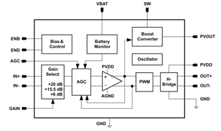
Regarding Uruno-san's question, the internal block diagram of the TPA2015D1 is as follows, and the connection between the ENB, END pins and VBAT cannot be confirmed.
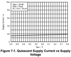
I see the confusion. The operating quiescent current when END & ENB are enabled on VBAT is what is specified in the DS and what I had reported through the plot and as 1.7mA to 2.2mA in this thread.
Just to be clear Kyohei, quiescent current measured on VBAT is 1.7mA to 2.2mA as reported by the DS. This quiescent current measurement is taken when the Class-D output and the boost mode of the output are enabled. There's a different measurement of 0.5mA when only the boost is enabled and Class-D output isn't.
Like the GAIN pin current measurements I took in this thread, I can repeat the same experiment for ENB and END pins. These values would be unspecified as well.
Expect a response on the current observed on those pins asap. The measurements would be for current measurement on ENB and END when there's an input at different gain levels.
The TPA2015 would definitely be able to meet the MCU's current rating at IOH 0.1mA & OL 0.4mA current drive. The current measurements recorded on my end are well below 0.1mA
Here are the measurements on ENB and END when equal to VBAT=5V at 1KHz on 8Ohm + 33uH with different gain pin configurations:
ENB:
float: 0.370uA +-0.02uA
hi: 0.400uA + 0.02uA
low: 0.365uA+- 0.02uA
I can conclude current draw on END pin is about 0.378uA on average.
END:
float: 0.550uA +-0.05uA
hi: 0.512uA +-0.05uA
low: 0.530uA +-0.05uA
END to shutdown pulls about 50uA
I can conclude current draw on pin END is about 0.530uA on average.
The gain pin measurements still remain at approximately 10uA. I would say it skewed +-0.05uA
I would also like to point out that on the EVM, to change the GAIN configuration, it's either it floats, it uses a straight shunt to VDD or GND while the ENB & END configurations require a 100Kohm to VDD for enabling or a straight shunt to GND for disabling. If using the operating VBAT range from 2.5V to 5.2V from the DS, the V=IR on these pins show a current pull of about 0.025mA to 0.052mA respectively. These values are within range of your current rating limits. So, you can also consider this as the range of current drawn on ENB & END.
I hope this resolves your questions and clears up the initial misunderstanding regarding the quiescent current as ENB & END. I collected lab data for better clarification, and it falls within range of the theory I could conclude from the EVM.