This thread has been locked.

If you have a related question, please click the "Ask a related question" button in the top right corner. The newly created question will be automatically linked to this question.

LM48560: Cin values and purpose for audio amplifiers

Part Number: LM48560
Other Parts Discussed in Thread: TAD5242

Tool/software:

Hi team,

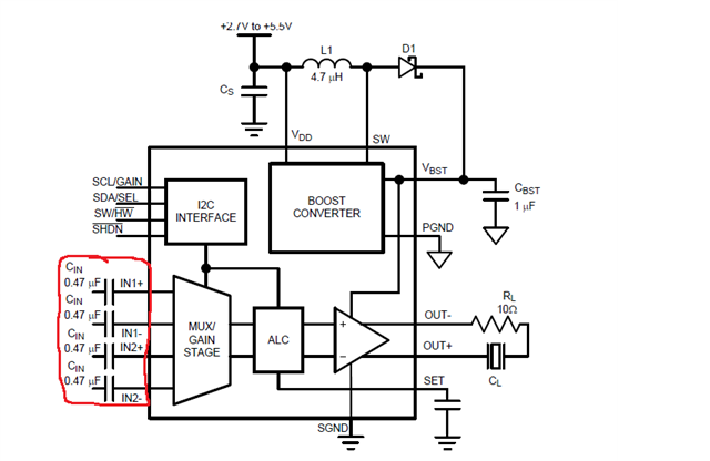
I am new to audio amplifiers and I am currently evaluating the LM48560. While reading the datasheet, I noticed that there is a 0.47uF capacitor located at every INX+ and INX- pins (X stands for 1 and 2).

I want to understand why do you guys decided to choose a 0.47uF capacitor on in series to the INX pin. What is the purpose of the Cin in general? Will 0.47uF be the recommended Cin value for LM48560?

Thank you so much for your patience!


Best Regards

Ena

  • The input capacitor acts as a high pass filter, if I am connecting it to a audio DAC output that has a low pass filter, does it mean that I am setting a frequency range the signal can go?

  • Hey Ena, 

    The input cap blocks DC current going through to the output as that would cause audible artifact. A cap at the input allows for only high frequency signals to pass through to the input.

    Regards,

    Ore.

  • Hi Ore,

    What value would you suggest to use for the caps at the input of the audio amplifier? The input comes from the output of the TAD5242 Stereo Audio DAC with a low pass filter along the output of the pins at 20MHz.

    Best Regards

    Ena

  • Hey Ena, 

    DC blocking caps can be a few microfarads (uF). I could suggest 0.1uF to 5uF. You want a cap value that small enough to block just DC. 

    The LPF on TAD5242 is allowing 20MHz or 20KHz? 20KHz is the audio band you want for audio applications. 

    Regards,

    Ore.

  • Hi Ore,

    Is it possible to explain why that value for the input capacitors? The LPF on TAD5242 is allowing 20KHz.

    Best Regards

    Ena

  • Hey Ena, 

    The DC blocking cap is technically creating a HPF for audio signals you want audible in your system. For the purpose of this thread, I would reference 10Hz as the lowest frequency of choice in my 20KHz audio band.

    I would start by noting the differential input resistance (Rin) which the DS reports as typically 50Kohms. Half this value and consider it the Rin.

    Then apply the Freq (-3dB drop) = 1/ (2piC*Rin) formula to give me my HPF filter cutoff frequency. Here, C = 0.64uF. This is in range of the choices mentioned above. DC Frequencies below 10Hz get blocked.

    Regards,

    Ore.