


Other Parts Discussed in Thread: DIR9001, , PCM5102, PCM2902
Tool/software:
Hello,
I recently started a new project that involves 4x DACs.
I usually use DIR9001 as a receiver and now i chose to get the PCM5142 due to the direct output.
In the past i used WM8740 but since power and simplicity is important now, PCM5102 or PCM5142 was more suited.
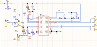
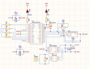
I used the same schematic as i usually do for the DIR9001 with a DA102JC transformer, ST3485EBD as a translator and made sure all the decoupling and filtering capacitors are present.
For the PCM5142 i used it in hardware mode only, and hooked it up next (actually 1 cm lower then the DIR9001) and start it up.
I had a PCM2902 sound card to get the Coax SPDIF output and everything was going great, until i hooked everything up to an amplifier and than i heard that the sound is clipping like hell....or it's distorted, as it's so bad that i can't make a difference. Once i stop the music a loud white noise is still on the background (normal operations) and i kind of hear some clicking (not really sure as it's short) like some clock it's entering the audio stream somehow.
I was tested also with the internal SCK as well with the DIR9001 SCK and the same issue is occuring.
In the past i played as well with PCM5102 and everything went really well. With the PCM5142 is not going as smooth as i though and i will need some suggestions on what to check....or maybe i did something wrong....
The decupling capacitors aren't in the pictures above but i definitely added them together with 10uF capacitors.
Thank you.
