This thread has been locked.

If you have a related question, please click the "Ask a related question" button in the top right corner. The newly created question will be automatically linked to this question.

PCM6240-Q1: Communication-related and gain-related

Part Number: PCM6240-Q1

Tool/software:

1.

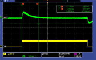
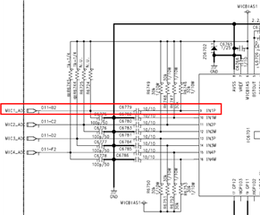
When the PCM6240 is not communicating with our system-on-a-chip (SOC) via TDM, the DC bias voltage at IN1P is 0.1V. When the PCM6240 communicates with our SOC via TDM (using TDM CLK), the DC bias voltage at IN1P rises to 0.7V and lasts for approximately 300ms. Is this phenomenon normal? Is a 0.7V bias voltage recommended for the design?


2.

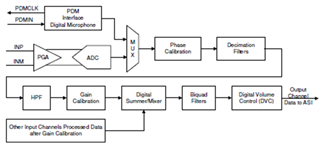
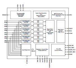
Does the PCM6240 have an internal fixed input attenuator with a known attenuation gain? The data sheet does not provide detailed descriptions of this. Does such a fixed attenuator exist? I cannot determine this from the diagrams either.


  • Hi Ye,

    1. The DC bias should be supplied at a DC voltage value that is half the swing of the input signal. For example with a 10 V-RMS signal (28.28Vpp) each pin will swing +/- 14.14V so to center the voltage swing correctly you set Vcm to 14.14/2 = 7.07V.

    The Vcm is set by the MICBIAS circuit for your single-ended inputs.

    2. There is an input attenuator in the design of this IC. This allows the device to support low and high swing input signals.

  • I'm so sorry. I guess I didn't accurately describe my question.

    ①What I'm measuring is the voltage of the AC

    In other words, the AC voltage rises from 0.1V to 0.7V after the start of TDM communication.

    This change is not related to MIC BIAS.Is it reasonable to set the AC voltage change.

    I would like to know how this input  attenuator, is set up, or what the default dB setting is?

    -8dB 0dB or +5dB?

    Can this setting be changed at a later stage.

    Thank you for your response.

  • Hi Ye,

    This AC voltage fluctuation may be due to your biasing setup, since MICBIAS is providing power to both the microphone and establishing the Vcm of the ADC after the 10uF capacitor. MICBIAS is sourcing current for both the ECM mic and is responsible for charging the large AC-coupling capacitor. The combination of both with large pull-up resistors (1k-30k) is likely affecting the charge time of the capacitor and RC time constant. I suspect this is what your seeing on your oscilloscope.

    Separating the power supplies here may resolve this issue. You can utilize MICBIAS after the capacitor to only establish the Vcm. 

    Or experimenting with a 1uF cap instead of 10uF and adjusting the size of the pull up resistors.

    The input attenuator is a fixed 14dB (since 2Vrms is 14dB less than 10Vrms) and is done internally. This cannot be adjusted.

  • I'm sorry to ask an additional question.

    What is the margin of error for input attenuator?

    ±5%?10%Or some other value

  • There is virtually no margin (<1%) for the input attenuator