This thread has been locked.

If you have a related question, please click the "Ask a related question" button in the top right corner. The newly created question will be automatically linked to this question.

PCM6360-Q1: ADC MIC output has attenuation

Part Number: PCM6360-Q1


Tool/software:

ADC MIC output has attenuation
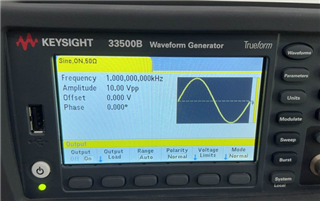
The values input to ADC MIC through the signal generator are shown in the following figure:


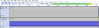
However, after passing through ADC MIC, there is a half attenuation in the output value, as shown in the following figure:


May I ask which configurations can be used to reduce or eliminate attenuation.

  • Hi,

    PCM6360 accepts up to a 10Vrms fully differential input signal, when this is converted to a digital (3.3V logic on SDOUT) signal then full-scale input is represented as 0dBFS. With a 10Vpp signal (~3.5Vrms) the digital output should be roughly -9dBFS. 

    I the audacity screen shot presented supposed to represent the digital output or analog input before its received by the ADC?

  • Hi,
    The audacity screen shot presented is digital output.
  • Hi Guilin,

    Apologies if I'm misunderstanding, the attenuation you're referring to in the audacity screenshot is not clear to me.

    Can you try providing a full scale input signal and log the response in audacity?

  • Hi,

    Our analog signal input can reach a maximum of 10Vpp,The digital signal recorded to the output is -6db when viewed with audacity.May I ask if this result is correct?

  • Can you share schematic?

    5Vrms (-6dB) the maximum input signal bandwidth for a single pin if the ADC front end is configured in single-ended configuration or the registers are configured this way. Ensure that the register configure the device for differential line input in high swing mode.

  • Our hardware is designed with the single-ended input connection.   May I ask what kind of impact this configuration usually causes?   Will the recorded sound be smaller than that of the differential input connection?

  • Hi.

    When a signal is differential the input provided to INP/M are the same but 180 degrees out of phase with each other so essentially a positive and negative input signal. This advantage of this is common mode noise rejection.

    Each pin supports a swing of +/- 5Vrms. So the total swing of a differential signal (2 pins - INP/M) is 10Vrms. When the input is single-ended, meaning you're only using one INP pin the max swing supported on the high voltage ADC is 5Vrms.

    This is typically represented in datasheets. Please see section 7.5 for this device