Other Parts Discussed in Thread: TLV320ADC6140
Tool/software:
Hi here.
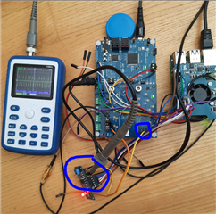
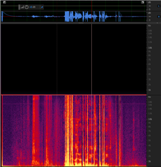
We are planing to use TLV320ADC5140 for our project. I'm fighting whit TVL320ADC5140 master + Raspberry Pi model 5 ---- 6.12.20+rpt-rpi-2712 in slave mode to get 4 TDM channels. What i get from them only one channel for recording.
All possible DTS configuration for dsp_a, I2S, tdm, left_j mode was tested, nothing except only one channel.
Here is my dts config:
:
/dts-v1/;
/plugin/;

/ {
//compatible = "brcm,bcm2712";
compatible = "brcm,bcm2712", "brcm,bcm2835";

// Enable I2C1 controller and connect the TLV320ADCx140
fragment@0 {
target = <&i2c1>;
__overlay__ {
#address-cells = <1>;
#size-cells = <0>;
status = "okay";

tlv320adcx140: tlv320adcx140@4c {
compatible = "ti,tlv320adc5140";
reg = <0x4c>;
#sound-dai-cells = <0>;
status = "okay";
// Optional reset line
// reset-gpios = <&gpio 4 0>;
};
};
};

// Enable I2S hardware block
fragment@1 {
target = <&i2s_clk_consumer>;
__overlay__ {
status = "okay";
};
};

// Define the virtual sound card
fragment@2 {
target = <&sound>;
__overlay__ {
compatible = "simple-audio-card";
status = "okay";

simple-audio-card,name = "TLV320ADC5140 Audio";
//simple-audio-card,format = "i2s";
simple-audio-card,format = "dsp_a";
//simple-audio-card,format = "left_j";
simple-audio-card,bitclock-master = <&codec_dai>;
simple-audio-card,frame-master = <&codec_dai>;

cpu_dai: simple-audio-card,cpu {
sound-dai = <&i2s_clk_consumer>;
dai-tdm-slot-num = <2>;
dai-tdm-slot-width = <32>;
//dai-tdm-slot-tx-mask = <1 1 1 1>;
//dai-tdm-slot-rx-mask = <1 1 1 1>;
};

codec_dai: simple-audio-card,codec {
sound-dai = <&tlv320adcx140>;
clocks = <&mclk_external>;
system-clock-direction-out = "out";
//system-clock-frequency = <12288000>;
//mclk-fs = <256>;
};
};
};
fragment@3 {
target-path = "/";
__overlay__ {
mclk_external: mclk_external {
compatible = "fixed-clock";
#clock-cells = <0>;
clock-frequency = <12288000>;
clock-output-names = "mclk";
};
};
};

fragment@4 {
target-path = "/";
__overlay__ {
debug;
linux,debug;
};
};


// Optional: enable i2s_clk_consumer
//fragment@3 {
// target-path = "/soc/i2s@7e203000";
// __overlay__ {
// status = "okay";
// };
// };

// Required overrides to resolve symbols
// __overrides__ {
// audio-codec = <&tlv320adcx140>,"reg";
// };
};
Alsa see the card and working with TVL320ADC5140, including changing value in corresponding registers. Interested fact that in bookworm 6.12.20+rpt-rpi-2712 no asound.conf and asoundrc files on corresponding folders.
Here is registry script (i could not past it as code):
#!/bin/bash
# TLV320ADC5140 Master Mode Initialization Script
ADDR=0x4C
BUS=1
OPTS="-y -f $BUS $ADDR"
# Function to write a register value on a specific page
i2c_write() {
PAGE=$1
REG=$2
VAL=$3
sudo i2cset $OPTS 0x00 $PAGE # Set page
sudo i2cset $OPTS $REG $VAL # Write value
}
echo "Configuring TLV320ADC5140 on I2C bus $BUS..."
########################
# Reset & Wake
########################
i2c_write 0x00 0x01 0x01 # Reset
sleep 1
i2c_write 0x00 0x02 0x81 # Enable adaptive filter + wake
i2c_write 0x00 0x05 0x05 # Enable all analog blocks
########################
# Channel Configs (1–4)
########################
# Channel 1 configuration
i2c_write 0x00 0x3C 0x21 # 0d = Microphone input
i2c_write 0x00 0x3D 0xA8 # 0d = Channel gain is set to 0 dB A8---42 max
i2c_write 0x00 0x3E 0xC9 # 0d = Digital volume is muted FF
i2c_write 0x00 0x3F 0x00 # 0d = Gain calibration is set to –0.8 dB
i2c_write 0x00 0x40 0x00 # 0d = No phase calibration
# Channel 2 configuration
i2c_write 0x00 0x41 0x21 # 0d = Microphone input
i2c_write 0x00 0x42 0xA8 # 0d = Channel gain is set to 0 dB
i2c_write 0x00 0x43 0xC9 # 0d = Digital volume
i2c_write 0x00 0x44 0x00 # 0d = Gain calibration is set to –0.8 dB
i2c_write 0x00 0x45 0x00 # 0d = No phase calibration
# Channel 3 configuration
i2c_write 0x00 0x46 0x21 # 0d = Microphone input
i2c_write 0x00 0x47 0xA8 # 0d = Channel gain is set to 0 dB
i2c_write 0x00 0x48 0xC9 # 0d = Digital volume
i2c_write 0x00 0x49 0x00 # 0d = Gain calibration is set to –0.8 dB
i2c_write 0x00 0x4A 0x00 # 0d = No phase calibration
# Channel 4 configuration
i2c_write 0x00 0x4B 0x21 # 0d = Microphone input
i2c_write 0x00 0x4C 0xA8 # 0d = Channel gain is set to 0 dB
i2c_write 0x00 0x4D 0xC9 # 0d = Digital volume
i2c_write 0x00 0x4E 0x00 # 0d = Gain calibration is set to –0.8 dB
i2c_write 0x00 0x4F 0x00 # 0d = No phase calibration
########################
# AGC & Input Bias
########################
i2c_write 0x00 0x70 0x00 # AGC: -6 dB target
i2c_write 0x00 0x6C 0x08 # AGC: Default attack/release
i2c_write 0x00 0x3B 0x02 # MIC bias = VREF (typ 2.75V)
########################
# Clocking (Master Mode, 12.288 MHz MCLK)
########################
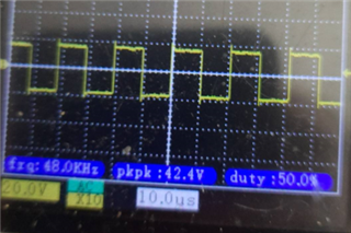
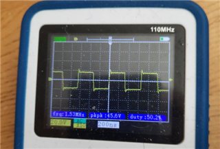
i2c_write 0x00 0x13 0x81 # BCLK, WCLK master B1 c1 81
i2c_write 0x00 0x14 0x42 # 48 kHz, 16bit
i2c_write 0x00 0x16 0x10 # PLL mode,
########################
# GPIO Config (Optional)
########################
i2c_write 0x00 0x33 0x00 # GPIO1 as input (can be used for MCLK detection) A0
########################
# ASI & TDM Configuration
########################
i2c_write 0x00 0x07 0x00 # 0d = TDM mode 00 = 16 bits 40 - i2s 80 -lj mode
i2c_write 0x00 0x08 0x00
i2c_write 0x00 0x09 0x00
# Channel mapping: CH1–CH4 to slots 0–3
i2c_write 0x00 0x0B 0x00
i2c_write 0x00 0x0C 0x01
i2c_write 0x00 0x0D 0x02
i2c_write 0x00 0x0E 0x03
########################
# GPIO Config (Optional)
########################
i2c_write 0x00 0x21 0xA0 # GPIO1 as input (can be used for MCLK detection) A0
########################
# Input/Output Channel Enable
########################
i2c_write 0x00 0x73 0xC0 # Enable input channels 1–4
i2c_write 0x00 0x74 0xC0 # Enable ASI output channels 1–4
# added as additional internal PPL config
i2c_write 0x00 0x1A 0x00
i2c_write 0x00 0x1B 0x00
#i2c_write 0x00 0x1D 0x00
#i2c_write 0x00 0x1C 0x00
# added as additional N Divider Disabled
i2c_write 0x00 0x1E 0x00
# added as additional M Divider Disabled
i2c_write 0x00 0x1F 0x00
# added as additional BCLK/FSYNC dividers
i2c_write 0x00 0x17 0x00
i2c_write 0x00 0x18 0x00
i2c_write 0x00 0x19 0x00
# added as additional PDM Configuration
#i2c_write 0x00 0x1F 0x40
#i2c_write 0x00 0x20 0x00
# added as additional clock error disable/enable
#i2c_write 0x00 0x04 0x40
# added as additional GPO config
#i2c_write 0x00 0x22 0x00
#i2c_write 0x00 0x23 0x00
#i2c_write 0x00 0x24 0x00
#i2c_write 0x00 0x25 0x00
#i2c_write 0x00 0x29 0x00
# added as additional GPI Configuration
#i2c_write 0x00 0x2B 0x00
#i2c_write 0x00 0x2C 0x00
#i2c_write 0x00 0x32 0x00
#i2c_write 0x00 0x33 0xFF
#i2c_write 0x00 0x3B 0x60
#DSP configuration
#i2c_write 0x00 0x6B 0x01
#i2c_write 0x00 0x6C 0x48
# DRE configuration
#i2c_write 0x00 0x6D 0x7B
# AGC Configuration
#i2c_write 0x00 0x70 0xE7
########################
# Final Power-Up
########################
i2c_write 0x00 0x00 0x00 # Select page 0
i2c_write 0x00 0x75 0xC0 # Power up MICBIAS, PLL, all ADCs
# added as additional N Divider Disabled
#i2c_write 0x00 0x1E 0x82
# added as additional M Divider Disabled
#i2c_write 0x00 0x1F 0xC0
echo "TLV320ADC5140 configuration complete."
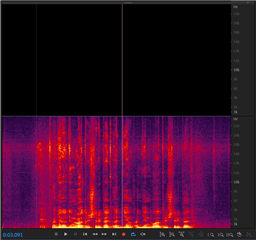
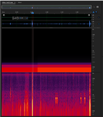
here is registry dump file 1) after scritp apply, during arecord command, after stop recording. Some registry changing value. For example reg 75 changing value C0---60---00
root@pi:/home/pi/ad9850# sudo i2cdump -y -f 1 0x4c
No size specified (using byte-data access)
0 1 2 3 4 5 6 7 8 9 a b c d e f 0123456789abcdef
00: 00 00 81 00 00 05 00 00 00 00 00 00 01 02 03 04 ..?..?......????
10: 05 06 07 81 42 ff 10 00 00 00 00 00 00 00 00 00 ????B.?.........
20: 00 a0 00 00 00 00 00 00 00 00 00 00 00 00 00 00 .?..............
30: 00 00 00 00 00 00 80 00 80 00 00 02 21 a8 c9 00 ......?.?..?!??.
40: 00 21 a8 c9 00 00 21 a8 c9 00 00 21 a8 c9 00 00 .!??..!??..!??..
50: 00 00 c9 80 00 00 00 c9 80 00 00 00 c9 80 00 00 ..??...??...??..
60: 00 c9 80 00 00 00 00 00 00 00 00 01 08 7b 00 00 .??........??{..
70: 00 00 00 c0 c0 c0 00 c0 00 00 ff 00 ff 8c 8c 00 ...???.?.....??.
80: 00 00 00 00 00 00 00 00 00 00 00 00 00 00 00 00 ................
90: 00 00 00 00 00 00 00 00 00 00 00 00 00 00 00 00 ................
a0: 00 00 00 00 00 00 00 00 00 00 00 00 00 00 00 00 ................
b0: 00 00 00 00 00 00 00 00 00 00 00 00 00 00 00 00 ................
c0: 00 00 00 00 00 00 00 00 00 00 00 00 00 00 00 00 ................
d0: 00 00 00 00 00 00 00 00 00 00 00 00 00 00 00 00 ................
e0: 00 00 00 00 00 00 00 00 00 00 00 00 00 00 00 00 ................
f0: 00 00 00 00 00 00 00 00 00 00 00 00 00 00 00 00 ................
root@pi:/home/pi/ad9850# sudo i2cdump -y -f 1 0x4c
No size specified (using byte-data access)
0 1 2 3 4 5 6 7 8 9 a b c d e f 0123456789abcdef
00: 00 00 81 00 00 05 00 04 00 00 00 00 01 02 03 04 ..?..?.?....????
10: 05 06 07 81 42 42 10 00 00 00 00 00 00 00 00 00 ????BB?.........
20: 00 a0 00 00 00 00 00 00 00 00 00 00 00 00 00 00 .?..............
30: 00 00 00 00 00 00 40 00 40 00 00 02 21 a8 c9 00 ......@.@..?!??.
40: 00 21 a8 c9 00 00 21 a8 c9 00 00 21 a8 c9 00 00 .!??..!??..!??..
50: 00 00 c9 80 00 00 00 c9 80 00 00 00 c9 80 00 00 ..??...??...??..
60: 00 c9 80 00 00 00 00 00 00 00 00 01 08 7b 00 00 .??........??{..
70: 00 00 00 f0 c0 60 f0 e0 00 00 ff 00 ff 8c a6 00 ...??`??.....??.
80: 00 00 00 00 00 00 00 00 00 00 00 00 00 00 00 00 ................
90: 00 00 00 00 00 00 00 00 00 00 00 00 00 00 00 00 ................
a0: 00 00 00 00 00 00 00 00 00 00 00 00 00 00 00 00 ................
b0: 00 00 00 00 00 00 00 00 00 00 00 00 00 00 00 00 ................
c0: 00 00 00 00 00 00 00 00 00 00 00 00 00 00 00 00 ................
d0: 00 00 00 00 00 00 00 00 00 00 00 00 00 00 00 00 ................
e0: 00 00 00 00 00 00 00 00 00 00 00 00 00 00 00 00 ................
f0: 00 00 00 00 00 00 00 00 00 00 00 00 00 00 00 00 ................
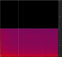
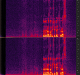
arecord -D hw:2,0 -f S16_LE -r 48000 -c 2 mastertest2ch_master_16_48.wav
root@pi:/home/pi/ad9850# sudo i2cdump -y -f 1 0x4c
No size specified (using byte-data access)
0 1 2 3 4 5 6 7 8 9 a b c d e f 0123456789abcdef
00: 00 00 81 00 00 05 00 04 00 00 00 00 01 02 03 04 ..?..?.?....????
10: 05 06 07 81 42 f2 10 00 00 00 00 00 00 00 00 00 ????B??.........
20: 00 a0 00 00 00 00 00 00 00 00 00 00 00 00 00 00 .?..............
30: 00 00 00 00 00 00 80 00 80 00 00 02 21 a8 c9 00 ......?.?..?!??.
40: 00 21 a8 c9 00 00 21 a8 c9 00 00 21 a8 c9 00 00 .!??..!??..!??..
50: 00 00 c9 80 00 00 00 c9 80 00 00 00 c9 80 00 00 ..??...??...??..
60: 00 c9 80 00 00 00 00 00 00 00 00 01 08 7b 00 00 .??........??{..
70: 00 00 00 00 c0 00 00 c0 00 00 ff 00 ff 8c 8b 00 ....?..?.....??.
80: 00 00 00 00 00 00 00 00 00 00 00 00 00 00 00 00 ................
90: 00 00 00 00 00 00 00 00 00 00 00 00 00 00 00 00 ................
a0: 00 00 00 00 00 00 00 00 00 00 00 00 00 00 00 00 ................
b0: 00 00 00 00 00 00 00 00 00 00 00 00 00 00 00 00 ................
c0: 00 00 00 00 00 00 00 00 00 00 00 00 00 00 00 00 ................
d0: 00 00 00 00 00 00 00 00 00 00 00 00 00 00 00 00 ................
e0: 00 00 00 00 00 00 00 00 00 00 00 00 00 00 00 00 ................
f0: 00 00 00 00 00 00 00 00 00 00 00 00 00 00 00 00 ................
Please help me whit dts/registry configuration for recording 2 and 4 channels
Thank you for help.