Tool/software:
Hello TI Support Team,
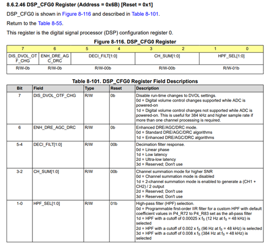
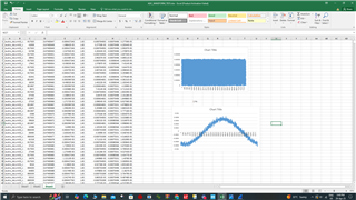
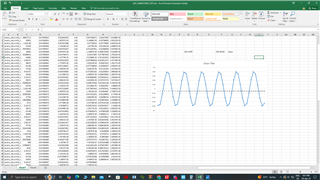
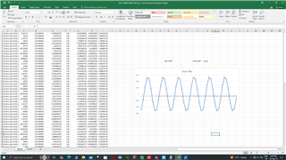
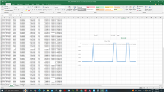
We are currently working on TLV320ADC5120 IC. As part of our testing, we applied a 1 Hz sine wave signal with 200 mVpp to the ADC input. The ADC output waveform correctly shows a sinusoidal shape, indicating that the sampling and processing path is functional.
However, we observed that the amplitude of the output data does not correspond to the expected level based on the 200 mVpp input. Attached a screenshots of the waveform plots and the corresponding data in Excel, where you can clearly see the sinusoidal shape but with an amplitude that appears significantly lower than expected.
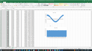
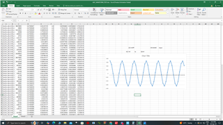
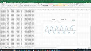
But when we have applied a 1 KHz with different voltage peak to peak, we have gotten a correct amplitude levels. which is shown in below screenshots,

Following is the register which we configure through i2c,
TLV320_WriteRegister(0x01, 0x01);
HAL_Delay(10);
TLV320_WriteRegister(0x02, 0x81);
HAL_Delay(10);
TLV320_WriteRegister(0x41, 0x40);
HAL_Delay(10);
TLV320_WriteRegister(0x3B, 0x70);
HAL_Delay(10);
TLV320_WriteRegister(0x22, 0x41);
HAL_Delay(10);
TLV320_WriteRegister(0x2B, 0x45);
HAL_Delay(10);
TLV320_WriteRegister(0x73, 0xF0);
HAL_Delay(10);
TLV320_WriteRegister(0x74, 0xF0);
HAL_Delay(10);
TLV320_WriteRegister(0x75, 0x60);
HAL_Delay(10);
-
Is there anyother register, we need to configure.
-
What could cause this discrepancy in amplitude despite the correct waveform shape in lower frequency?
-
Are there any specific gain, scaling, or PGA settings we should double-check?
-
Could any filtering or digital processing within the TLV320ADC5120 be influencing the observed output amplitude?
We look forward to your guidance. Thanks in advance.
Best regards,
Ajith Kumar