This thread has been locked.

If you have a related question, please click the "Ask a related question" button in the top right corner. The newly created question will be automatically linked to this question.

PCM6360-Q1: Communication abnormality

Part Number: PCM6360-Q1

Tool/software:

 Dear team,

I am using PCM6360-Q1.The i2c communication between PCM6360 and MCU is abnormal.

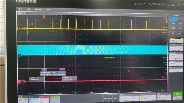
The MCU can send the correct TDM clock to PCM6360, but PCM6360 did not collect data and provide feedback to the MCU.

The data has no waveform. But the input of the simulated mic test is okay,it can be measured when speaking.

The registers during collection are as follows. Is there a problem with which register setting?

root@auto8678p164sos:/sys/kernel/debug/regmap/1-0048-pcm6340# cat registers 

00: 00

01: 00

02: 81

03: 00

04: 00

05: 05

06: 00

07: 00

08: 01

09: 00

0a: 00

0b: 00

0c: 00

0d: 00

0e: 00

0f: 04

10: 05

11: 06

12: 07

13: 00

14: 48

15: 46

16: 10

17: 10

18: 04

19: 20

1a: 02

1b: 08

1c: 00

1d: 00

1e: 02

1f: 40

20: 00

21: 22

22: 00

23: 00

24: 00

25: 00

26: 00

27: 00

28: 00

29: ff

2a: 03

2b: 00

2c: 80

2d: 00

2e: 00

2f: 00

30: 00

31: 00

32: 00

33: 00

34: 00

35: 00

36: 00

37: 00

38: ba

39: 4b

3a: 10

3b: d0

3c: 10

3d: 00

3e: c9

3f: 80

40: 00

41: 10

42: 00

43: c9

44: 80

45: 00

46: 10

47: 00

48: c9

49: 80

4a: 00

4b: 10

4c: 00

4d: c9

4e: 80

4f: 00

50: 10

51: 00

52: c9

53: 80

54: 00

55: 10

56: 00

57: c9

58: 80

59: 00

5a: 00

5b: 00

5c: c9

5d: 80

5e: 00

5f: 00

60: 00

61: c9

62: 80

63: 00

64: 00

65: 37

66: 87

67: b8

68: 00

69: 00

6a: 00

6b: 01

6c: 48

6d: 7b

6e: 00

6f: 00

70: e7

71: 00

72: 00

73: fc

74: 00

75: 00

76: 00

77: c0

78: 00

79: 00

7a: ff

7b: 00

7c: ff

7d: 98

7e: 88

7f: 00

80: 00

root@auto8678p164sos:/s

2、Does PCM6360 need MCLK?

  • Hi, 

    PCM6360 does not need an MCLK if operating in slave/target mode

    To troubleshoot hardware, please verify the following: Ensure the power supply rails (AVDD,IOVDD,HVDD) are stable, power outputs (AREG,DREG) are stable, and the clocks are correct (FSYNC/BCLK). Your BCLK should be  #Ch * bit depth * sampling rate.. For example 6Ch * 32bit depth * 48kHz Fs = 9.216MHz BCLK.

    Here an example script for TDM mode, 6 channel recording, 32bit depth, dc coupled mic input

    # CHECKSUM 0
    # -----------------------------------------------------------------------------
    # Reset
    # -----------------------------------------------------------------------------
    # Select Page 0
    w 90 00 00
    # Reset Device
    w 90 01 01
    # 1mS Delay
    # -----------------------------------------------------------------------------
    # Begin Device Memory
    # -----------------------------------------------------------------------------
    # Page 0 (0x00) Dump
    # Select Page 0
    w 90 00 00
    w 90 02 81
    # Input Channel Enable
    w 90 74 fc
    # Power up/down
    # Select page 0
    w 90 00 00
    w 90 75 a0


  • Hi,

    Thanks. 

    Our hardware platform adopts AC single ended mode, using 4ch,32bit,48k.

    May I ask about the register timing of AC single ended mode. Also, if there is no waveform in the data, are there any debugging methods?

    For example, which registers can be used to view the cause of the fault.

  • Hi,

    Attached a modified script below. Typical errors are made through the troubleshooting tips i mentioned earlier, but you can also read register 0x15h to ensure the ASI bus is detecting the clock input correctly

    # CHECKSUM 0
    # -----------------------------------------------------------------------------
    # Reset
    # -----------------------------------------------------------------------------
    # Select Page 0
    w 90 00 00
    # Reset Device
    w 90 01 01
    # 1mS Delay
    # -----------------------------------------------------------------------------
    # Begin Device Memory
    # -----------------------------------------------------------------------------
    # Page 0 (0x00) Dump
    # Select Page 0
    w 90 00 00
    w 90 02 81
    # Micbias Configuration
    w 90 3b f0
    # CH1 CFG, Gain, Volume, Gain cal, phase cal
    w 90 3c a0
    # CH2 CFG, Gain, Volume, Gain cal, phase cal
    w 90 41 a0
    # CH3 CFG, Gain, Volume, Gain cal, phase cal
    w 90 46 b0
    # CH4 CFG, Gain, Volume, Gain cal, phase cal
    w 90 4b b0
    # Input Channel Enable
    w 90 73 f0
    w 90 74 f0
    # Power up/down
    # Select page 0
    w 90 00 00
    w 90 75 80


    If possible can you attach schematic?